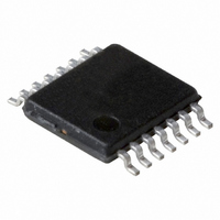
PCF2123TS/1,118 NXP Semiconductors, PCF2123TS/1,118 Datasheet - Page 20

PCF2123TS/1,118
Manufacturer Part Number
PCF2123TS/1,118
Description
IC SPI RTC/CALENDAR 14TSSOP
Manufacturer
NXP Semiconductors
Type
Clock/Calendar/Alarmr
Specifications of PCF2123TS/1,118
Package / Case
14-TSSOP
Time Format
HH:MM:SS (12/24 hr)
Date Format
YY-MM-DD-dd
Interface
SPI, 3-Wire Serial
Voltage - Supply
1.1 V ~ 5.5 V
Operating Temperature
-40°C ~ 85°C
Mounting Type
Surface Mount
Function
Clock/Calendar
Supply Voltage (max)
5.5 V
Supply Voltage (min)
1.1 V
Maximum Operating Temperature
+ 85 C
Minimum Operating Temperature
- 40 C
Mounting Style
SMD/SMT
Rtc Bus Interface
Serial (3-Wire, SPI)
Lead Free Status / RoHS Status
Lead free / RoHS Compliant
Memory Size
-
Lead Free Status / Rohs Status
Lead free / RoHS Compliant
Other names
568-4534-2
935286384118
PCF2123TS/1-T
935286384118
PCF2123TS/1-T
Available stocks
Company
Part Number
Manufacturer
Quantity
Price
Company:
Part Number:
PCF2123TS/1,118
Manufacturer:
VISHAY
Quantity:
15 160
Part Number:
PCF2123TS/1,118
Manufacturer:
NXP/恩智浦
Quantity:
20 000
NXP Semiconductors
PCF2123
Product data sheet
The generation of interrupts from the alarm function is controlled via bit AIE (register
Control_2, see
will remain set until cleared by the interface. Once AF has been cleared, it will only be set
again when the time increments to match the alarm condition once more. Alarm registers
which have their AE_x bit logic 1 are ignored.
Generation of interrupts from the alarm function is described in
Figure
and bit TF unaffected. The flags are cleared by a write command, therefore bits 7, 6, 4, 1
and 0 must be written with their previous values. Repeatedly re-writing these bits has no
influence on the functional behavior.
To prevent the timer flags being overwritten while clearing bit AF, logic AND is performed
during a write access. A flag is cleared by writing logic 0 whilst a flag is not cleared by
writing logic 1. Writing logic 1 will result in the flag value remaining unchanged.
Table 22.
Table 23
bit TF are unaffected.
Table 23.
Register
Control_2
Register
Control_2
Fig 13. Alarm flag timing
13,
shows what instruction must be sent to clear bit AF. In this example, bit MSF and
Example where only the minute alarm is used and no other interrupts are enabled.
Table 22
Flag location in register Control_2
Example to clear only AF (bit 3) in register Control_2
Table
Bit
7
-
Bit
7
-
All information provided in this document is subject to legal disclaimers.
INT when AIE = 1
minutes counter
minute alarm
and
7). If bit AIE is enabled, the INT pin follows the condition of bit AF. AF
Rev. 4 — 22 December 2010
Table 23
6
-
6
-
AF
44
45
show an example for clearing bit AF, but leaving bit MSF
5
MSF
5
1
4
-
4
-
45
3
AF
3
0
SPI Real time clock/calendar
2
TF
2
1
Section
001aaf903
46
PCF2123
© NXP B.V. 2010. All rights reserved.
1
-
1
-
8.7.3.
0
-
0
-
20 of 61


