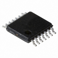
PCF2123TS/1,118 NXP Semiconductors, PCF2123TS/1,118 Datasheet - Page 6

PCF2123TS/1,118
Manufacturer Part Number
PCF2123TS/1,118
Description
IC SPI RTC/CALENDAR 14TSSOP
Manufacturer
NXP Semiconductors
Type
Clock/Calendar/Alarmr
Specifications of PCF2123TS/1,118
Package / Case
14-TSSOP
Time Format
HH:MM:SS (12/24 hr)
Date Format
YY-MM-DD-dd
Interface
SPI, 3-Wire Serial
Voltage - Supply
1.1 V ~ 5.5 V
Operating Temperature
-40°C ~ 85°C
Mounting Type
Surface Mount
Function
Clock/Calendar
Supply Voltage (max)
5.5 V
Supply Voltage (min)
1.1 V
Maximum Operating Temperature
+ 85 C
Minimum Operating Temperature
- 40 C
Mounting Style
SMD/SMT
Rtc Bus Interface
Serial (3-Wire, SPI)
Lead Free Status / RoHS Status
Lead free / RoHS Compliant
Memory Size
-
Lead Free Status / Rohs Status
Lead free / RoHS Compliant
Other names
568-4534-2
935286384118
PCF2123TS/1-T
935286384118
PCF2123TS/1-T
Available stocks
Company
Part Number
Manufacturer
Quantity
Price
Company:
Part Number:
PCF2123TS/1,118
Manufacturer:
VISHAY
Quantity:
15 160
Part Number:
PCF2123TS/1,118
Manufacturer:
NXP/恩智浦
Quantity:
20 000
NXP Semiconductors
8. Functional description
PCF2123
Product data sheet
8.1.1 Power consumption with respect to quartz series resistance
8.1 Low power operation
The PCF2123 contains 16 8-bit registers with an auto-incrementing address counter, an
on-chip 32.768 kHz oscillator with two integrated load capacitors, a frequency divider
which provides the source clock for the Real Time Clock (RTC), a programmable clock
output, and a 6.25 Mbit/s SPI-bus. An offset register allows fine tuning of the clock.
All 16 registers are designed as addressable 8-bit parallel registers although not all bits
are implemented.
Minimum power operation will be achieved by reducing the number and frequency of
switching signals inside the IC, i.e., low frequency timer clocks and a low frequency
CLKOUT will result in lower operating power. A second prime consideration is the series
resistance R
The series resistance acts as a loss element. Low R
further.
•
•
•
•
•
•
The first two registers (memory address 00h and 01h) are used as control registers.
The memory addresses 02h through 08h are used as counters for the clock function
(seconds up to years). The registers Seconds, Minutes, Hours, Days, Weekdays,
Months, and Years are all coded in Binary Coded Decimal (BCD) format. When one of
the RTC registers is written or read the contents of all counters are frozen. Therefore,
faulty writing or reading of the clock and calendar during a carry condition is
prevented.
Addresses 09h through 0Ch define the alarm condition.
Address 0Dh defines the offset calibration.
Address 0Eh defines the clock out and timer mode.
Address registers 0Eh and 0Fh are used for the countdown timer function. The
countdown timer has four selectable source clocks allowing for countdown periods in
the range from 244 s up to four hours. There are also two pre-defined timers which
can be used to generate an interrupt once per second or once per minute. These are
defined in register Control_2 (01h).
s
of the quartz used.
All information provided in this document is subject to legal disclaimers.
Rev. 4 — 22 December 2010
s
will reduce current consumption
SPI Real time clock/calendar
PCF2123
© NXP B.V. 2010. All rights reserved.
6 of 61


