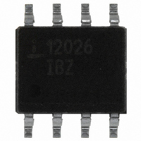
ISL12026IBZ Intersil, ISL12026IBZ Datasheet - Page 21

ISL12026IBZ
Manufacturer Part Number
ISL12026IBZ
Description
IC RTC/CALENDAR EEPROM 8-SOIC
Manufacturer
Intersil
Type
Clock/Calendar/EEPROMr
Specifications of ISL12026IBZ
Memory Size
4K (512 x 8)
Time Format
HH:MM:SS (12/24 hr)
Date Format
YY-MM-DD-dd
Interface
I²C, 2-Wire Serial
Voltage - Supply
2.7 V ~ 5.5 V
Operating Temperature
-40°C ~ 85°C
Mounting Type
Surface Mount
Package / Case
8-SOIC (3.9mm Width)
Clock Format
HH
Clock Ic Type
RTC
Interface Type
I2C, Serial
Memory Configuration
512 X 8
Supply Voltage Range
2.7V To 5.5V
Digital Ic Case Style
SOIC
Rohs Compliant
Yes
Lead Free Status / RoHS Status
Lead free / RoHS Compliant
Available stocks
Company
Part Number
Manufacturer
Quantity
Price
Company:
Part Number:
ISL12026IBZ
Manufacturer:
INTELSEL
Quantity:
60
Part Number:
ISL12026IBZ
Manufacturer:
INTERSIL
Quantity:
20 000
Part Number:
ISL12026IBZ-T
Manufacturer:
INTERSIL
Quantity:
20 000
minimizes this by running the IRQ/F
the X1 and X2 pins. Also, reducing the switching current at
this pin by careful selection of the pull-up resistor value will
reduce noise. Intersil suggests a minimum value of 5.1kΩ for
32.768kHz, and higher values (up to 20kΩ) for lower
frequency IRQ/F
For other RTC products, the same rules stated above should
be observed, but adjusted slightly since the
packages and pinouts are different.
Oscillator Measurements
When a proper crystal is selected and the layout guidelines
above are observed, the oscillator should start up in most
circuits in less than one second. Some circuits may take
slightly longer, but startup should definitely occur in less than
5 seconds. When testing RTC circuits, the most common
impulse is to apply a scope probe to the circuit at the X2 pin
(oscillator output) and observe the waveform. DO NOT DO
THIS! Although in some cases you may see a useable
waveform, due to the parasitics (usually 10pF to ground)
applied with the scope probe, there will be no useful
information in that waveform other than the fact that the
circuit is oscillating. The X2 output is sensitive to capacitive
impedance so the voltage levels and the frequency will be
affected by the parasitic elements in the scope probe.
Applying a scope probe can possibly cause a faulty oscillator
to start up, hiding other issues (although in the Intersil RTCs,
the internal circuitry assures startup when using the proper
crystal and layout).
The best way to analyze the RTC circuit is to power it up and
read the real time clock as time advances, or if the chip has
the IRQ/F
oscilloscope (after enabling it with the control register, and
using a pull-up resistor for an open-drain output).
Alternatively, the ISL12026 device has an IRQ/F
which can be checked by setting an alarm for each minute.
Using the pulse interrupt mode setting, the once-per-minute
interrupt functions as an indication of proper oscillation.
Backup Battery Operation
Many types of batteries can be used with the Intersil RTC
products. 3.0V or 3.6V Lithium batteries are appropriate, and
sizes are available that can power a Intersil RTC device for
up to 10 years. Another option is to use a supercapacitor for
applications where V
short periods of time. Depending on the value of
supercapacitor used, backup time can last from a few days
to two weeks (with >1F). A simple silicon or Schottky barrier
diode can be used in series with V
supercapacitor, which is connected to the V
use Schottky diodes with very low leakages, <1
Do not use the diode to charge a battery (especially lithium
batteries!).
There are two possible modes for battery backup operation,
Standard and Legacy mode. In Standard mode, there are no
OUT
output, look at the output of that pin on an
OUT
DD
outputs.
may disappear intermittently for
21
DD
OUT
to charge the
output away from
BAT
µA
pin. Try to
OUT
desirable.
output
ISL12026
operational concerns when switching over to battery backup
since all other devices functions are disabled. Battery drain
is minimal in Standard mode, and return to Normal V
powered operations is predictable. In Legacy mode the V
pin can power the chip if the voltage is above V
than V
communicate with the device, unless SBI = 1, but the supply
current drain is much higher than the Standard mode and
backup time is reduced. In this case if alarms are used in
backup mode, the IRQ/F
connected to V
the default mode is the Standard mode.
Alarm Operation Examples
Below are examples of both Single Event and periodic
Interrupt Mode alarms.
Example 1 – Alarm 0 set with single interrupt (IM = ”0”)
A single alarm will occur on January 1 at 11:30am.
A. Set Alarm 0 registers as follows:
B. Also the AL0E bit must be set as follows:
After these registers are set, an alarm will be generated when
the RTC advances to exactly 11:30am on January 1 (after
REGISTER
REGISTER
CONTROL
ALARM0
2.7-5.5V
MNA0
MOA0
DWA0
HRA0
SCA0
DTA0
INT
FIGURE 24. SUPERCAPACITOR CHARGING CIRCUIT
TRIP
.
,
In this mode, it is possible to generate alarm and
7 6 5 4 3 2 1 0 HEX
0 0 0 0 0 0 0 0
1 0 1 1 0 0 0 0
1 0 0 1 0 0 0 1
1 0 0 0 0 0 0 1
1 0 0 0 0 0 0 1
0 0 0 0 0 0 0 0
7 6 5 4 3 2 1 0 HEX
0 0 1 0 0 0 0 0
BAT
V
voltage source. During initial power up
CC
V
OUT
SS
BIT
BIT
V
back
pull up resistor must be
00h Seconds disabled
B0h Minutes set to 30,
91h Hours set to 11,
81h Date set to 1,
81h Month set to 1,
00h Day of week
x0h Enable Alarm
enabled
enabled
enabled
enabled
disabled
DESCRIPTION
Supercapacitor
DESCRIPTION
DD
October 23, 2006
and less
DD
FN8231.5
BAT


