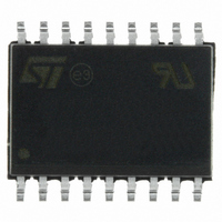
M41T81SMY6E STMicroelectronics, M41T81SMY6E Datasheet - Page 22

M41T81SMY6E
Manufacturer Part Number
M41T81SMY6E
Description
IC RTC SER W/ALARMS 18-SOIC
Manufacturer
STMicroelectronics
Type
Clock/Calendar/Alarmr
Datasheet
1.M41T81SM6F.pdf
(32 pages)
Specifications of M41T81SMY6E
Memory Size
20B
Time Format
HH:MM:SS:hh (24 hr)
Date Format
YY-MM-DD-dd
Interface
I²C, 2-Wire Serial
Voltage - Supply
2.7 V ~ 5.5 V
Operating Temperature
-40°C ~ 85°C
Mounting Type
Surface Mount
Package / Case
18-SOIC (7.5mm Width)
Lead Free Status / RoHS Status
Lead free / RoHS Compliant
Clock operation
Output driver pin
Note:
Preferred initial power-on default
1. BMB0-BMB4, RB0, RB1
2. State of other control bits undefined
3. UC = Unchanged
22/32
Initial power-up
Subsequent power-up
(with battery backup)
Condition
When the FT bit, AFE bit, SQWE bit, and watchdog register are not set, the
IRQ/FT/OUT/SQW pin becomes an output driver that reflects the contents of D7 of the
calibration register. In other words, when D7 (OUT bit) and D6 (FT bit) of address location
08h are a '0,' then the IRQ/FT/OUT/SQW pin will be driven low.
The IRQ/FT/OUT/SQW pin is an open drain which requires an external pull-up resistor.
Upon initial application of power to the device, the following register bits are set to a '0' state:
watchdog register; AFE; ABE; SQWE; OFIE; and FT. The following bits are set to a '1' state:
ST; OUT; OF; and HT (see
Table 5.
(2)
(3)
Preferred default values
UC
ST
1
HT
Table
1
1
Doc ID 10773 Rev 6
Out
UC
5).
1
FT
0
0
AFE SQWE ABE
UC
0
UC
0
UC
0
WATCHDOG
register
0
0
(1)
UC
OF
1
M41T81S
OFIE
UC
0


