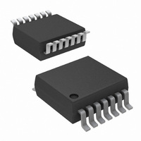
ISL12029IV27AZ Intersil, ISL12029IV27AZ Datasheet - Page 10

ISL12029IV27AZ
Manufacturer Part Number
ISL12029IV27AZ
Description
IC RTC/CALENDAR EEPROM 14-TSSOP
Manufacturer
Intersil
Type
Clock/Calendar/Supervisor/EEPROMr
Datasheet
1.ISL12029IBZ-T.pdf
(29 pages)
Specifications of ISL12029IV27AZ
Memory Size
4K (512 x 8)
Time Format
HH:MM:SS (12/24 hr)
Date Format
YY-MM-DD-dd
Interface
I²C, 2-Wire Serial
Voltage - Supply
2.7 V ~ 5.5 V
Operating Temperature
-40°C ~ 85°C
Mounting Type
Surface Mount
Package / Case
14-TSSOP
Lead Free Status / RoHS Status
Lead free / RoHS Compliant
is back to V
the V
X1, X2
The X1 and X2 pins are the input and output, respectively, of
an inverting amplifier. An external 32.768kHz quartz crystal is
used with the ISL12029 to supply a timebase for the real time
clock. Internal compensation circuitry provides high accuracy
over the operating temperature range from -40°C to +85°C.
This oscillator compensation network can be used to calibrate
the crystal timing accuracy over-temperature either during
manufacturing or with an external temperature sensor and
microcontroller for active compensation. X2 is intended to
drive a crystal only, and should not drive any external circuit.
No external compensation resistors or capacitors are
needed or are recommended to be connected to the X1 and
X2 pins.
Real Time Clock Operation
The Real Time Clock (RTC) uses an external 32.768kHz
quartz crystal to maintain an accurate internal representation
of the second, minute, hour, day, date, month, and year. The
RTC has leap-year correction. The clock also corrects for
months having fewer than 31 days and has a bit that controls
24 hour or AM/PM format. When the ISL12029 powers up
after the loss of both V
operate until at least one byte is written to the clock register.
Reading the Real Time Clock
The RTC is read by initiating a Read command and
specifying the address corresponding to the register of the
Real Time Clock. The RTC Registers can then be read in a
Sequential Read Mode. Since the clock runs continuously
and read takes a finite amount of time, there is a possibility
that the clock could change during the course of a read
operation. In this device, the time is latched by the read
command (falling edge of the clock on the ACK bit prior to
RTC data output) into a separate latch to avoid time changes
during the read operation. The clock continues to run.
Alarms occurring during a read are unaffected by the read
operation.
Writing to the Real Time Clock
The time and date may be set by writing to the RTC
registers. RTC Register should be written ONLY with Page
Write. To avoid changing the current time by an uncompleted
write operation, write to the all 8 bytes in one write operation.
When writing the RTC registers, the new time value is
loaded into a separate buffer at the falling edge of the clock
FIGURE 11. RECOMMENDED CRYSTAL CONNECTION
DD
voltage is above V
DD
mode (out of Battery Backup mode) even if
DD
and V
RESET
10
BAT
X1
X2
threshold.
, the clock will not
ISL12029, ISL12029A
during the Acknowledge. This new RTC value is loaded into
the RTC Register by a stop bit at the end of a valid write
sequence. An invalid write operation aborts the time update
procedure and the contents of the buffer are discarded. After
a valid write operation the RTC will reflect the newly loaded
data beginning with the next “one second” clock cycle after
the stop bit is written. The RTC continues to update the time
while an RTC register write is in progress and the RTC
continues to run during any non-volatile write sequences.
Accuracy of the Real Time Clock
The accuracy of the Real Time Clock depends on the
accuracy of the quartz crystal that is used as the time base
for the RTC. Since the resonant frequency of a crystal is
temperature dependent, the RTC performance will also be
dependent upon temperature. The frequency deviation of
the crystal is a function of the turnover-temperature of the
crystal from the crystal’s nominal frequency. For example, a
>20ppm frequency deviation translates into an accuracy of
>1 minute per month. These parameters are available from
the crystal manufacturer. Intersil’s RTC family provides
on-chip crystal compensation networks to adjust
load-capacitance to tune oscillator frequency from -34ppm to
+80ppm when using a 12.5pF load crystal. For more detailed
information, see “Application Section” on page 23.
Clock/Control Registers (CCR)
The Control/Clock Registers are located in an area separate
from the EEPROM array and are only accessible following a
slave byte of “1101111x” and reads or writes to addresses
[0000h:003Fh]. The clock/control memory map has memory
addresses from 0000h to 003Fh. The defined addresses are
described in Table 2. Writing to and reading from the
undefined addresses are not recommended.
CCR Access
The contents of the CCR can be modified by performing a
byte or a page write operation directly to any address in the
CCR. Prior to writing to the CCR (except the status register),
however, the WEL and RWEL bits must be set using a three
step process (See “Writing to the Clock/Control Registers”
on page 15.)
The CCR is divided into 5 sections. These are:
Each register is read and written through buffers. The
non-volatile portion (or the counter portion of the RTC) is
updated only if RWEL is set and only after a valid write
operation and stop bit. A sequential read or page write
operation provides access to the contents of only one
section of the CCR per operation. Access to another section
1. Alarm 0 (8 bytes; non-volatile)
2. Alarm 1 (8 bytes; non-volatile)
3. Control (5 bytes; non-volatile)
4. Real Time Clock (8 bytes; volatile)
5. Status (1 byte; volatile)
December 16, 2010
FN6206.10


