ISL12029IV27AZ Intersil, ISL12029IV27AZ Datasheet
ISL12029IV27AZ
Specifications of ISL12029IV27AZ


Related parts for ISL12029IV27AZ

ISL12029IV27AZ Summary of contents
Page 1
... GND internal connection 1 BlockLock™ trademark of Intersil Corporation or one of its subsidiaries. Copyright Intersil Americas Inc. 2005, 2006, 2008, 2010. December 16, 2010 2 C Bus™ Features • Real Time Clock/Calendar - Tracks Time in Hours, Minutes and Seconds - Day of the Week, Day, Month and Year - 3 Selectable Frequency Outputs • ...
Page 2
Block Diagram X1 32.768kHZ X2 IRQ/F SELECT OUT CONTROL SCL SERIAL DECODE INTERFACE LOGIC DECODER SDA 8 RESET Pin Descriptions PIN NUMBER SYMBOL 1 X1 The X1 pin is the input of an inverting amplifier and is intended to be ...
Page 3
... PART MARKING ISL12029IB27Z 12029IB27Z ISL12029IB27AZ 12029IB27 AZ ISL12029IB30AZ 12029IB30 AZ ISL12029IBZ 12029IBZ ISL12029IBAZ 12029IBAZ ISL12029IV27Z 12029 IV27Z ISL12029IV27AZ 12029 27AZ ISL12029IV30AZ 12029 30AZ ISL12029IVZ 12029 IVZ ISL12029IVAZ 12029 IVAZ ISL12029AIB27Z 12029AIB 27Z ISL12029AIV27Z 2029A IV27Z NOTES: 1. Add “-T*” suffix for tape and reel. Please refer to 2 ...
Page 4
... Ld SOIC Package (Notes TSSOP Package (Note Maximum Junction Temperature (Plastic Package +150°C Storage Temperature . . . . . . . . . . . . . . . . . . . . . . . .-65°C to +150°C Pb-Free Reflow Profile .see link below http://www.intersil.com/pbfree/Pb-FreeReflow.asp = +2.7V to +5.5V 3.3V. Boldface limits apply over the operating temperature range, -40°C to +85°C. DD ...
Page 5
Watchdog Timer/Low Voltage Reset Parameters SYMBOL PARAMETER t V Detect to RESET LOW RPD DD t Power-Up Reset Time-Out Delay PURST V Minimum VDD for Valid RESET RVALID Output V ISL12029-4.5A Reset Voltage Level RESET ISL12029 Reset Voltage Level ISL12029-3 ...
Page 6
Serial Interface (I C) Specifications - DC/AC Characteristics SYMBOL PARAMETER t Clock HIGH Time HIGH t START Condition Setup Time SU:STA t START Condition Hold Time HD:STA t Input Data Setup Time SU:DAT t Input Data Hold Time HD:DAT ...
Page 7
Timing Diagrams SCL t SU:STA t HD:STA SDA (INPUT TIMING) SDA (OUTPUT TIMING) SCL SDA 8TH BIT OF LAST BYTE t RSP SCL SDA RESET START Note: All inputs are ignored during the active reset period (t V RESET V ...
Page 8
Typical Performance Curves 4.0 BSW = 3.5 SCL, SDA PULL-UPS = 0V 3.0 2.5 2.0 1.5 SCL, SDA PULL-UPS = V 1.0 0.5 BSW = 0.0 1.8 2.3 2.8 3.3 3.8 V (V) BAT ...
Page 9
Description The ISL12029 device is a Real Time Clock with clock/calendar, two polled alarms with integrated 512x8 EEPROM, oscillator compensation, CPU Supervisor (Power-on Reset, Low Voltage Sensing and Watchdog Timer) and battery backup switch. The oscillator uses an external, low-cost ...
Page 10
... For example, a >20ppm frequency deviation translates into an accuracy of >1 minute per month. These parameters are available from the crystal manufacturer. Intersil’s RTC family provides on-chip crystal compensation networks to adjust load-capacitance to tune oscillator frequency from -34ppm to +80ppm when using a 12.5pF load crystal. For more detailed information, see “ ...
Page 11
A read or write can begin at any address in the CCR not necessary to set the RWEL bit prior to writing the status register. Section 5 (status register) supports a single byte read ...
Page 12
V and 0V). The bit is set DD BAT regardless of whether applied first. The loss DD BAT of only one of the supplies does not set the RTCF bit ...
Page 13
Unused Bits: Bit 3 in the SR is not used, but must be zero. The Data Byte output during a SR read will contain a zero in this bit location. Alarm Registers (Non-Volatile) Alarm0 and Alarm1 The alarm register bytes ...
Page 14
CRYSTAL OSCILLATOR FIGURE 12. DIAGRAM OF ATR The effective on-chip series load capacitance, C ranges from 4.5pF to 20.25pF with a mid-scale value of 12.5pF (default changed via two digitally LOAD controlled ...
Page 15
TABLE 6. V SELECT BITS RESET VTS2 VTS1 VTS0 battery mode, the RESET signal output is asserted LOW when the V voltage supply has ...
Page 16
... Many types of batteries can be used with Intersil RTC products. For example, 3.0V or 3.6V Lithium batteries are appropriate, and battery sizes are available that can power an Intersil RTC device for years. Another option is to use a SuperCap for applications where V for month. See “Application Section” on page 23 for more information ...
Page 17
OPTION 2 - LEGACY POWER CONTROL MODE (DEFAULT FOR ISL12029) The Legacy Mode follows conditions set in X1226 products. In this mode, switching from BAT comparing the voltages and the device operates from whichever is the ...
Page 18
See “I C Communications During Battery Backup and LVR Operation” on page 25. In battery mode, the RESET signal output is asserted LOW when the V voltage supply has dipped below the V DD threshold. The RESET signal ...
Page 19
In the read mode, the device will transmit 8 bits of data, release the SDA line, then monitor the line for an acknowledge acknowledge is detected and no stop condition is generated by the master, the device will ...
Page 20
Write Operations Byte Write For a write operation, the device requires the Slave Address Byte and the Word Address Bytes. This gives the master access to any one of the words in the array or CCR. (Note: Prior to writing ...
Page 21
S T SIGNALS FROM A THE MASTER R T ADDRESS SDA BUS 1 SIGNALS FROM THE SLAVE Acknowledge Polling Disabling of the inputs during non-volatile write cycles can be used to take advantage of the typical 5ms write cycle ...
Page 22
It should be noted, that the ninth clock cycle of the read operation is not a “don’t care.” To terminate a read operation, the master must either issue a stop condition during the ninth cycle or hold SDA HIGH during ...
Page 23
... In addition to the analog compensation afforded by the adjustable load capacitance, a digital compensation feature is available for the Intersil RTC family. There are 3 bits known as the Digital Trimming Register or DTR, and they operate by adding or skipping pulses in the clock signal. The range provided is ± ...
Page 24
... Many types of batteries can be used with the Intersil RTC C1 C1 products. 3.0V or 3.6V Lithium batteries are appropriate, and 0.1µF sizes are available that can power a Intersil RTC device for up 0.1µ years. Another option is to use a supercapacitor for applications where V periods of time. Depending on the value of supercapacitor used, backup time can last from a few days to two weeks (with > ...
Page 25
I C Communications During Battery Backup and LVR Operation Operation in Battery Backup mode and LVR is affected by the BSW and SBIB bits as described earlier. These bits allow flexible operation of the serial bus and EEPROM in ...
Page 26
V (3.0V) BAT (2.63V) RESET V TRIP (2.2V) RESET I BAT (V FIGURE 29. EXAMPLE RESET OPERATION IN MODE (3.0V) BAT (2.63V) RESET V TRIP (2.2V) RESET I BAT Alarm ...
Page 27
... Accordingly, the reader is cautioned to verify that data sheets are current before placing orders. Information furnished by Intersil is believed to be accurate and reliable. However, no responsibility is assumed by Intersil or its subsidiaries for its use; nor for any infringements of patents or other rights of third parties which may result from its use ...
Page 28
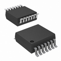
Package Outline Drawing M14.15 14 LEAD NARROW BODY SMALL OUTLINE PLASTIC PACKAGE Rev 1, 10/09 14 3 PIN NO.1 ID MARK 5 0.31-0.51 0. A-B D TOP VIEW 1.75 MAX 1.27 SIDE VIEW ...
Page 29
Package Outline Drawing M14.173 14 LEAD THIN SHRINK SMALL OUTLINE PACKAGE (TSSOP) Rev 3, 10/09 1 5.00 ±0.10 14 6.40 4.40 ±0. 0. 0.65 TOP VIEW H C SEATING PLANE 0.10 C SIDE VIEW ...