X9401WS24IZ-2.7T1 Intersil, X9401WS24IZ-2.7T1 Datasheet - Page 4
X9401WS24IZ-2.7T1
Manufacturer Part Number
X9401WS24IZ-2.7T1
Description
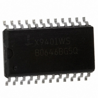
IC POT DGTL QUAD 10K OHM 24-SOIC
Manufacturer
Intersil
Series
XDCP™r
Datasheet
1.X9401WS24ZT1.pdf
(18 pages)
Specifications of X9401WS24IZ-2.7T1
Taps
64
Resistance (ohms)
10K
Number Of Circuits
4
Temperature Coefficient
300 ppm/°C Typical
Memory Type
Non-Volatile
Interface
SPI, 3-Wire Serial
Voltage - Supply
2.7 V ~ 5.5 V
Operating Temperature
-40°C ~ 85°C
Mounting Type
Surface Mount
Package / Case
24-SOIC (7.5mm Width)
Resistance In Ohms
10K
Lead Free Status / RoHS Status
Lead free / RoHS Compliant
Other names
X9401WS24IZ-2.7T1TR
Available stocks
Company
Part Number
Manufacturer
Quantity
Price
Company:

Part Number:
X9401WS24IZ-2.7T1
Manufacturer:
IDT
Quantity:
3 067


Data Registers
Each potentiometer has four 6-bit nonvolatile data registers.
These can be read or written directly by the host. Data can
also be transferred between any of the four data registers
and the associated Wiper Counter Register. All operations
changing data in one of the data registers is a nonvolatile
operation and will take a maximum of 10ms.
If the application does not require storage of multiple
settings for the potentiometer, the data registers can be used
as memory locations for system parameters or user
preference data.
DATA REGISTER DETAIL
Write in Process
The contents of the Data Registers are saved to nonvolatile
memory when the CS pin goes from LOW to HIGH after a
complete write sequence is received by the device. The
progress of this internal write operation can be monitored by
a Write In Process bit (WIP). The WIP bit is read with a Read
Status command.
Instructions
Identification (ID) Byte
The first byte sent to the X9401 from the host, following a CS
going HIGH to LOW, is called the Identification byte. The
most significant four bits of the slave address are a device
type identifier. For the X9401 this is fixed as 0101[B] (refer to
Figure 1).
The two least significant bits in the ID byte select one of four
devices on the bus. The physical device address is defined
by the state of the A
the serial data stream with the address input state; a
successful compare of both address bits is required for the
X9401 to successfully continue the command sequence.
The A
signals or tied to V
slave byte must be set to 0.
(MSB)
NV
D5
0
- A
FIGURE 1. IDENTIFICATION BYTE FORMAT
0
1
inputs can be actively driven by CMOS input
DEVICE TYPE
IDENTIFIER
NV
D4
1
CC
0
0
- A
or V
D3
NV
1
SS
input pins. The X9401 compares
1
. The remaining two bits in the
4
0
NV
D2
0
DEVICE ADDRESS
A1
NV
D1
A0
(LSB)
NV
D0
X9401
Instruction Byte
The next byte sent to the X9401 contains the instruction and
register pointer information. The four most significant bits are
the instruction. The next four bits point to one of the four pots
and, when applicable, they point to one of four associated
registers. The format is shown below in Figure 2.
I
The four high order bits of the instruction byte specify the
operation. The next two bits (R
four registers that is to be acted upon when a register
oriented instruction is issued. The last two bits (P1 and P
selects which one of the four potentiometers is to be affected
by the instruction.
Four of the ten instructions are two bytes in length and end
with the transmission of the instruction byte. These
instructions are:
• XFR Data Register to Wiper Counter Register: This
• XFR Wiper Counter Register to Data Register: This
• Global XFR Data Register to Wiper Counter Register: This
• Global XFR Wiper Counter Register to Data
The basic sequence of the two byte instructions is illustrated
in Figure 3. These two-byte instructions exchange data
between the WCR and one of the data registers. A transfer
from a data register to a WCR is essentially a write to a static
RAM, with the static RAM controlling the wiper position. The
response of the wiper to this action will be delayed by t
A transfer from the WCR (current wiper position), to a data
register is a write to nonvolatile memory and takes a
minimum of t
between one of the four potentiometers and one of its
associated registers; or it may occur globally, where the
transfer occurs between all potentiometers and one
associated register.
Five instructions require a three-byte sequence to complete.
These instructions transfer data between the host and the
X9401; either between the host and one of the data registers
transfers the contents of one specified Data Register to
the associated Wiper Counter Register.
transfers the contents of the specified Wiper Counter
Register to the specified associated Data Register.
transfers the contents of all specified Data Registers to the
associated Wiper Counter Registers.
Register: This transfers the contents of all Wiper Counter
Registers to the specified associated Data Registers.
FIGURE 2. IDENTIFICATION BYTE FORMAT
I3
WR
INSTRUCTIONS
I2
to complete. The transfer can occur
I1
I0
1
R1
and R
R0
0
) select one of the
POT SELECT
P1
October 13, 2009
P0
FN8190.4
WRL
0
)
.
Related parts for X9401WS24IZ-2.7T1
Image
Part Number
Description
Manufacturer
Datasheet
Request
R

Part Number:
Description:
IC DCP QUAD 10K 64TP 24SOIC
Manufacturer:
Intersil
Datasheet:

Part Number:
Description:
IC DCP QUAD 10K 64TP 24SOIC
Manufacturer:
Intersil
Datasheet:
Part Number:
Description:
IC XDCP QUAD 64-TAP 10K 24-SOIC
Manufacturer:
Intersil
Datasheet:
Part Number:
Description:
IC DCP QUAD 10K 64TP 24SOIC
Manufacturer:
Intersil
Datasheet:
Part Number:
Description:
IC DCP QUAD 10K 64TP 24SOIC
Manufacturer:
Intersil
Datasheet:
Part Number:
Description:
IC XDCP QUAD 64-TAP 10K 24-SOIC
Manufacturer:
Intersil
Datasheet:

Part Number:
Description:
Intersil Corporation [CMOS Serial Controller Interface]
Manufacturer:
Intersil Corporation
Datasheet:
Part Number:
Description:
Manufacturer:
Intersil Corporation
Datasheet:
Part Number:
Description:
357-036-542-201 CARDEDGE 36POS DL .156 BLK LOPRO
Manufacturer:
Intersil Corporation
Datasheet:
Part Number:
Description:
1024-Word x 4-Bit LSI Static RAM
Manufacturer:
Intersil Corporation
Datasheet:
Part Number:
Description:
General Purpose NPN Transistor Arrays FN341.4
Manufacturer:
Intersil Corporation
Datasheet:
Part Number:
Description:
CMOS 16-Bit Microprocessor
Manufacturer:
Intersil Corporation
Datasheet:
Part Number:
Description:
Manufacturer:
Intersil Corporation
Datasheet:
Part Number:
Description:
Manufacturer:
Intersil Corporation
Datasheet:
Part Number:
Description:
Manufacturer:
Intersil Corporation
Datasheet: