DSPB56362AG120 Freescale Semiconductor, DSPB56362AG120 Datasheet - Page 110
DSPB56362AG120
Manufacturer Part Number
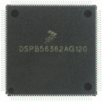
DSPB56362AG120
Description
IC DSP 24BIT AUD 120MHZ 144-LQFP
Manufacturer
Freescale Semiconductor
Series
Symphony™r
Type
Audio Processorr
Datasheet
1.DSPB56362AG120.pdf
(152 pages)
Specifications of DSPB56362AG120
Interface
Host Interface, I²C, SAI, SPI
Clock Rate
120MHz
Non-volatile Memory
ROM (126 kB)
On-chip Ram
42kB
Voltage - I/o
3.30V
Voltage - Core
3.30V
Operating Temperature
-40°C ~ 85°C
Mounting Type
Surface Mount
Package / Case
144-LQFP
Device Core Size
24b
Architecture
Modified Harvard
Format
Fixed Point
Clock Freq (max)
120MHz
Mips
120
Device Input Clock Speed
120MHz
Ram Size
42KB
Program Memory Size
90KB
Operating Supply Voltage (typ)
3.3V
Operating Supply Voltage (min)
3.14V
Operating Supply Voltage (max)
3.46V
Operating Temp Range
-40C to 105C
Operating Temperature Classification
Industrial
Mounting
Surface Mount
Pin Count
144
Package Type
LQFP
Product
DSPs
Data Bus Width
24 bit
Processor Series
DSP563xx
Core
56000
Numeric And Arithmetic Format
Fixed-Point
Instruction Set Architecture
Modified Harvard
Device Million Instructions Per Second
120 MIPS
Maximum Clock Frequency
120 MHz
Program Memory Type
Flash
Data Ram Size
42 KB
Operating Supply Voltage
3.3 V
Maximum Operating Temperature
+ 105 C
Mounting Style
SMD/SMT
Interface Type
SPI, I2C, ESAI, SHI
Minimum Operating Temperature
- 40 C
Lead Free Status / RoHS Status
Lead free / RoHS Compliant
Available stocks
Company
Part Number
Manufacturer
Quantity
Price
Company:

Part Number:
DSPB56362AG120
Manufacturer:
FSC
Quantity:
12 000
Company:
Part Number:
DSPB56362AG120
Manufacturer:
FREESCA
Quantity:
273
Company:
Part Number:
DSPB56362AG120
Manufacturer:
Freescale Semiconductor
Quantity:
10 000
Part Number:
DSPB56362AG120
Manufacturer:
N/A
Quantity:
20 000


Electrical Design Considerations
As noted above, the junction-to-case thermal resistances quoted in this data sheet are determined using the
first definition. From a practical standpoint, that value is also suitable for determining the junction
temperature from a case thermocouple reading in forced convection environments. In natural convection,
using the junction-to-case thermal resistance to estimate junction temperature from a thermocouple
reading on the case of the package will estimate a junction temperature slightly hotter than actual
temperature. Hence, the new thermal metric, thermal characterization parameter or Ψ
to be (T
when using the surface temperature of the package. Remember that surface temperature readings of
packages are subject to significant errors caused by inadequate attachment of the sensor to the surface and
to errors caused by heat loss to the sensor. The recommended technique is to attach a 40-gauge
thermocouple wire and bead to the top center of the package with thermally conductive epoxy.
5.2
Use the following list of recommendations to assure correct DSP operation:
5-2
•
•
•
•
•
•
•
•
To minimize temperature variation across the surface, the thermal resistance is measured from the
junction to the outside surface of the package (case) closest to the chip mounting area when that
surface has a proper heat sink.
To define a value approximately equal to a junction-to-board thermal resistance, the thermal
resistance is measured from the junction to where the leads are attached to the case.
If the temperature of the package case (T
is computed using the value obtained by the equation
Provide a low-impedance path from the board power supply to each V
the board ground to each GND pin.
Use at least six 0.01–0.1 µF bypass capacitors positioned as close as possible to the four sides of
the package to connect the V
Ensure that capacitor leads and associated printed circuit traces that connect to the chip V
GND pins are less than 1.2 cm (0.5 inch) per capacitor lead.
Use at least a four-layer PCB with two inner layers for V
Because the DSP output signals have fast rise and fall times, PCB trace lengths should be minimal.
This recommendation particularly applies to the address and data buses as well as the IRQA,
IRQB, IRQC, IRQD, TA, and BG pins. Maximum PCB trace lengths on the order of 15 cm
(6 inches) are recommended.
J
– T
Electrical Design Considerations
T
)/P
(T
This device contains circuitry protecting against damage due to high static
voltage or electrical fields. However, normal precautions should be taken to
avoid exceeding maximum voltage ratings. Reliability of operation is
enhanced if unused inputs are tied to an appropriate logic voltage level (e.g.,
either GND or V
is 10 k ohm.
J
D
– T
. This value gives a better estimate of the junction temperature in natural convection
T
)/P
D
.
CC
). The suggested value for a pullup or pulldown resistor
CC
DSP56362 Technical Data, Rev. 4
power source to GND.
CAUTION
T
) is determined by a thermocouple, the thermal resistance
CC
and GND.
CC
pin on the DSP and from
Freescale Semiconductor
JT
, has been defined
CC
and
Related parts for DSPB56362AG120
Image
Part Number
Description
Manufacturer
Datasheet
Request
R

Part Number:
Description:
Manufacturer:
Freescale Semiconductor, Inc
Datasheet:
Part Number:
Description:
Manufacturer:
Freescale Semiconductor, Inc
Datasheet:
Part Number:
Description:
Manufacturer:
Freescale Semiconductor, Inc
Datasheet:
Part Number:
Description:
Manufacturer:
Freescale Semiconductor, Inc
Datasheet:
Part Number:
Description:
Manufacturer:
Freescale Semiconductor, Inc
Datasheet:
Part Number:
Description:
Manufacturer:
Freescale Semiconductor, Inc
Datasheet:
Part Number:
Description:
Manufacturer:
Freescale Semiconductor, Inc
Datasheet:
Part Number:
Description:
Manufacturer:
Freescale Semiconductor, Inc
Datasheet:
Part Number:
Description:
Manufacturer:
Freescale Semiconductor, Inc
Datasheet:
Part Number:
Description:
Manufacturer:
Freescale Semiconductor, Inc
Datasheet:
Part Number:
Description:
Manufacturer:
Freescale Semiconductor, Inc
Datasheet:
Part Number:
Description:
Manufacturer:
Freescale Semiconductor, Inc
Datasheet:
Part Number:
Description:
Manufacturer:
Freescale Semiconductor, Inc
Datasheet:
Part Number:
Description:
Manufacturer:
Freescale Semiconductor, Inc
Datasheet:
Part Number:
Description:
Manufacturer:
Freescale Semiconductor, Inc
Datasheet: