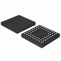
0W633-001-XTP ON Semiconductor, 0W633-001-XTP Datasheet - Page 24

0W633-001-XTP
Manufacturer Part Number
0W633-001-XTP
Description
IC AUDIO PROCESSOR AD/DA 57LFBGA
Manufacturer
ON Semiconductor
Series
BelaSigna® 250r
Type
Floating Pointr
Datasheet
1.B250W48A106XXG.pdf
(33 pages)
Specifications of 0W633-001-XTP
Interface
I²C, I²S, PCM, SPI, UART
Clock Rate
50MHz
On-chip Ram
42kB
Voltage - I/o
1.0V, 2.0V
Voltage - Core
1.00V, 2.00V
Operating Temperature
-40°C ~ 85°C
Mounting Type
Surface Mount
Package / Case
57-LFBGA
Package
57CABGA
Numeric And Arithmetic Format
Fixed-Point
Ram Size
16 KB
Lead Free Status / RoHS Status
Lead free / RoHS Compliant
Non-volatile Memory
-
Available stocks
Company
Part Number
Manufacturer
Quantity
Price
Company:
Part Number:
0W633-001-XTP
Manufacturer:
MAXIM
Quantity:
4 300
Company:
Part Number:
0W633-001-XTP
Manufacturer:
ON Semiconductor
Quantity:
10 000
In this process the program ROM checks the bootloader for
validity, which in turn ensures the file system validity. If the
file structure is validated, the bootloader is written to
PRAM. In case of an error while reading the external
EEPROM, all outputs are muted. The system restarts
approximately every second and attempts to reboot.
counter is set to point to the beginning of the bootloader
Power Management Strategy
guarantees valid system operation under any voltage supply
condition to prevent any unexpected audio output as the
result of any supply irregularity. The unit constantly
monitors the power supply and shuts down all functional
units (including all units in the audio path) when the power
supply voltage goes below a level at which point valid
operation can no longer be guaranteed.
Once the supply voltage rises above the startup voltage of
the internal regulator that supplies the digital subsystems
(VDDC
T
POR
Once the bootloader is loaded into PRAM the program
BelaSigna 250 has a built−in power management unit that
The power supply operation can be seen in Figure 10.
, a POR will occur. If the supply is consistent, the
Program Memory
STARTUP
Boot ROM
Boot ROM loads Bootloader
from EEPROM to Program
Memory
) and remains there for the length of time
Stage 1:
Bootloader
Application
EEPROM
MDA
SDA
FAT
Program Memory
Figure 9. Booting Sequence
Bootloader loads Application from
EEPROM to Program Memory, X
Memory, and Y Memory
Bootloader
Boot ROM
http://onsemi.com
Time
Stage 2:
24
code. Subsequently, the signal−processing application that
is stored in the EEPROM is downloaded to PRAM by the
bootloader. The boot process generally takes less than one
second. ON Semiconductor provides a standard full−feature
bootloader. A graphical representation of this booting
sequence can be seen in Figure 9.
internal system voltage will then remain at a fixed nominal
voltage (VDDC
voltage to drop below the shutdown internal system voltage
(VDDC
voltage rises again above the startup voltage and remains
there for the length of time T
operating directly off a battery, the system will not power
down until the voltage drops below the VDDC
voltage as the battery dies. This prevents unwanted resets
when the voltage is just on the edge of being too low for the
system to operate properly because the difference between
VDDC
around the VDDC
Application
Bootloader
EEPROM
MDA
SDA
FAT
STARTUP
SHUTDOWN
NOMINAL
and VDDC
SHUTDOWN
), the system will shut down. If the
Program Memory
Bootloader
Application
Boot ROM
Application loaded and running
). If a spike occurs that causes the
SHUTDOWN
point.
POR
Stage 3:
, a POR will occur. If
prevents oscillation
Application
Bootloader
EEPROM
MDA
SDA
FAT
SHUTDOWN


