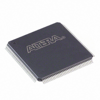
EP1C3T144A8N Altera, EP1C3T144A8N Datasheet - Page 46

EP1C3T144A8N
Manufacturer Part Number
EP1C3T144A8N
Description
IC CYCLONE FPGA 2910 LE 144-TQFP
Manufacturer
Altera
Series
Cyclone®r
Datasheet
1.EP1C3T100A8N.pdf
(47 pages)
Specifications of EP1C3T144A8N
Number Of Logic Elements/cells
2910
Number Of Labs/clbs
291
Total Ram Bits
59904
Number Of I /o
104
Voltage - Supply
1.425 V ~ 1.575 V
Mounting Type
Surface Mount
Operating Temperature
0°C ~ 85°C
Package / Case
144-TQFP, 144-VQFP
Lead Free Status / RoHS Status
Lead free / RoHS Compliant
Number Of Gates
-
Available stocks
Company
Part Number
Manufacturer
Quantity
Price
Company:
Part Number:
EP1C3T144A8N
Manufacturer:
ALTERA
Quantity:
248
Part Number:
EP1C3T144A8N
Manufacturer:
ALTERA
Quantity:
20 000
7–4
Pin-Out Information
Package and Board Layout Information
The Automotive-Grade Device Handbook
f
■
Table 7–2. Minimum DLL Frequency
■
■
■
For the maximum I/O clock toggle rate specifications in commercial-grade Stratix II
devices of –5 speed, refer to the
the Stratix II Device Handbook.
■
For details on the HardCopy II device pin-outs, refer to the
Files
For package-related information (for example, dimensions and thermal resistance
values) on HardCopy II devices, refer to the
Sheet.
For PCB design guidelines, refer to
for Altera
The delay-locked loop (DLL ) frequency range is bounded by the minimum
frequencies listed in
Table 7–2
Non-calibrated on-chip termination (OCT) is bounded by:
■
■
Hot-socketing DC limit is raised to 350 µA.
The I/O f
their equivalent industrial-grade HardCopy II devices and correspond to the
commercial-grade Stratix II devices of –5 speed. The I/O f
industrial-grade HardCopy II devices will be updated in a later revision of the
and Switching Specifications and Operating Conditions
HardCopy Series Handbook.
For LVDS I/O of 2.5 V, the minimum V
240 mV.
web page.
±40% for series resistance.
±50% for 1.2-V series resistance.
Devices.
MAX
shows the minimum DLL frequency for each frequency mode.
Frequency Mode 0
Frequency Mode 1
Frequency Mode 2
Frequency Mode 3
values of automotive-grade HardCopy II devices are 15% lower than
Mode
Table
7–2.
DC and Switching Characteristics
AN114: Designing With High-Density BGA Packages
OCM
Altera Device Package Information Data
is 1.1 V and the minimum V
chapter in volume 1 of the
Frequency (MHz)
HardCopy Device Pin-Out
© March 2010 Altera Corporation
MAX
Chapter 7: HardCopy II Devices
120
170
220
270
chapter in volume 1 of
values of the
Pin-Out Information
OD
is
DC


