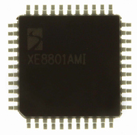
XE8801AMI027LF Semtech, XE8801AMI027LF Datasheet - Page 110

XE8801AMI027LF
Manufacturer Part Number
XE8801AMI027LF
Description
IC DAS 16BIT FLASH 8K MTP 44LQFP
Manufacturer
Semtech
Datasheet
1.XE8801AMI027LF.pdf
(135 pages)
Specifications of XE8801AMI027LF
Applications
Sensing Machine
Core Processor
RISC
Program Memory Type
FLASH (22 kB)
Controller Series
XE8000
Ram Size
512 x 8
Interface
UART, USRT
Number Of I /o
24
Voltage - Supply
2.4 V ~ 5.5 V
Operating Temperature
-40°C ~ 85°C
Mounting Type
Surface Mount
Package / Case
44-LQFP
For Use With
XE8000MP - PROG BOARD AND PROSTART2 CARD
Lead Free Status / RoHS Status
Lead free / RoHS Compliant
Available stocks
Company
Part Number
Manufacturer
Quantity
Price
- Current page: 110 of 135
- Download datasheet (2Mb)
As an example, consider the system where: GD
5V. In this case, the noise contribution V
V
Considering a 0.2V (rms) maximum signal amplitude, the signal-to-noise ratio is 90dB.
Noise can also be reduced by implementing a software filter. By making an average on a number of subsequent
measurements, the apparent noise is reduced the square root of the number of measurement used to make the
average.
16.8.5
Gain error is defined as the amount of deviation between the ideal transfer function (theoretical equation Eq. 18) and
the measured transfer function (with the offset error removed).
The actual gain of the different stages can vary depending on the fabrication tolerances of the different elements.
Although these tolerances are specified to a maximum of ±3%, they will be most of the time around ±0.5%.
Moreover, the tolerances between the different stages are not correlated and the probability to get the maximal error
in the same direction in all stages is very low. Finally, these gain errors can be calibrated by the software at the same
time with the gain errors of the sensor for instance.
© Semtech 2005
N,IN
= 6.4µV (rms) at the input of the acquisition chain, or, equivalently, 0.85 LSB at the output of the ADC.
Gain Error and Offset Error
Figure 16-17 ADC noise (PGA1, 2 & 3 bypassed, OSR=512,N
Figure 16-18 (a) Simple noise model for PGAs and ADC
V
PGA1
N,IN
GD1
PGA1
GD1
80
60
40
20
V
0
N1
and (b) total input referred noise
N1
-5
of PGA1 is dominant over that of PGA2. Using equation Eq. 21, we get:
-4
Output Code Deviation From Mean Value [LSB]
PGA2
GD2
2
-3
= 10 (GD
PGA2
GD2
-2
V
N2
16-25
(b)
-1
(a)
1
0
= 1; PGA3 bypassed), OSR = 512, N
PGA3
GD3
PGA3
GD3
1
V
2
N3
3
ADC
ADC
4
f
f
S
S
5
XE8801A – SX8801R
ELCONV
=2)
www.semtech.com
ELCONV
= 2, V
REF
=
Related parts for XE8801AMI027LF
Image
Part Number
Description
Manufacturer
Datasheet
Request
R

Part Number:
Description:
EVALUATION BOARD
Manufacturer:
Semtech
Datasheet:

Part Number:
Description:
EVALUATION BOARD
Manufacturer:
Semtech
Datasheet:

Part Number:
Description:
VOLTAGE SUPPRESSOR, TRANSIENT SEMTECH
Manufacturer:
Semtech
Datasheet:

Part Number:
Description:
HIGH VOLTAGE CAPACITORS MONOLITHIC CERAMIC TYPE
Manufacturer:
Semtech Corporation
Datasheet:

Part Number:
Description:
EZ1084CM5.0 AMP POSITIVE VOLTAGE REGULATOR
Manufacturer:
Semtech Corporation
Datasheet:

Part Number:
Description:
3.0 AMP LOW DROPOUT POSITIVE VOLTAGE REGULATORS
Manufacturer:
Semtech Corporation
Datasheet:

Part Number:
Description:
Manufacturer:
Semtech Corporation
Datasheet:

Part Number:
Description:
RailClamp Low Capacitance TVS Diode Array
Manufacturer:
Semtech Corporation
Datasheet:

Part Number:
Description:
Manufacturer:
Semtech Corporation
Datasheet:

Part Number:
Description:
Manufacturer:
Semtech Corporation
Datasheet:

Part Number:
Description:
Manufacturer:
Semtech Corporation
Datasheet:

Part Number:
Description:
Manufacturer:
Semtech Corporation
Datasheet:


