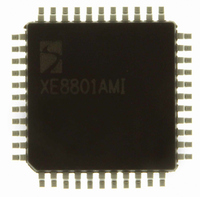
XE8801AMI027LF Semtech, XE8801AMI027LF Datasheet - Page 68

XE8801AMI027LF
Manufacturer Part Number
XE8801AMI027LF
Description
IC DAS 16BIT FLASH 8K MTP 44LQFP
Manufacturer
Semtech
Datasheet
1.XE8801AMI027LF.pdf
(135 pages)
Specifications of XE8801AMI027LF
Applications
Sensing Machine
Core Processor
RISC
Program Memory Type
FLASH (22 kB)
Controller Series
XE8000
Ram Size
512 x 8
Interface
UART, USRT
Number Of I /o
24
Voltage - Supply
2.4 V ~ 5.5 V
Operating Temperature
-40°C ~ 85°C
Mounting Type
Surface Mount
Package / Case
44-LQFP
For Use With
XE8000MP - PROG BOARD AND PROSTART2 CARD
Lead Free Status / RoHS Status
Lead free / RoHS Compliant
Available stocks
Company
Part Number
Manufacturer
Quantity
Price
XE8801A – SX8801R
12.6 Port B function capability
The Port B can be used for different functions implemented by other peripherals. The description below is
applicable only in so far the circuit contains these peripherals.
When the counters are used to implement a PWM function (see the documentation of the counters), the PB[0] and
PB[1] terminals are used as outputs (PB[0] is used if CntPWM0 in RegCntConfig1 is set to 1, PB[1] is used if
CntPWM1 in RegCntConfig1 is set to 1) and the PWM generated values overwrite the values written in
RegPBout. However, PBDir(0) and PBDir(1) are not automatically overwritten and have to be set to 1.
If OutputCkXtal is set in RegSysMisc, the Xtal clock is output on PB[3] (EnableXtal in RegSysClock must be set
to 1). This overrides the value contained in PBOut(3). However, PBDir(3) must be set to 1. The duty cycle of the
clock signal is about 50%.
Similarly, if OutputCkCpu is set in RegSysMisc, the CPU frequency is output on PB[2]. This overrides the value
contained in PBOut(2). However, PBDir(2) must be set to 1.
The frequency of the CPU clock depends on the selection of the CpuSel bit in the RegSysClock register (see
clock_gen_ff).
Pins PB[5] and PB[4] can be used for S1 and S0 of the USRT (see USRT documentation) when the UsrtEnable bit
is set in RegUsrtCtrl. The PB[5] and PB[4] then become open-drain. This overrides the values contained in
PBOpen(5:4), PBOut(5:4) and PBDir(5:4). If there is no external pull-up resistor on these pins, internal pull-ups
should be selected by setting PBPullup(5:4). When S0 is an output, the pin PB[4] takes the value of UsrtS0 in
RegUrstS0. When S1 is an output, the pin PB[5] takes the value of UsrtS1 in RegUrstS1.
Pins PB[6] and PB[7] can be used by the UART (see UART documentation). When UartEnTx in RegUartCtrl is set
to 1, PB[6] is used as output signal Tx. When UartEnRx in RegUartCtrl is set to 1, PB[7] is used as input signal
Rx. This overrides the values contained in PBOut(7:6) and PBDir(7:6).
12.7 Port B digital capabilities
12.7.1
Port B digital configuration
The direction of each bit within Port B (input only or input/output) can be individually set using the RegPBDir
register. If PBDir[x] = 1, both the input and output buffer are active on the corresponding Port B. If PBDir[x] = 0,
the corresponding Port B pin is an input only and the output buffer is in high impedance. After reset (resetpconf)
Port B is in input only mode (PBDir[x] are reset to 0).
The input values of Port B are available in RegPBIn (read only). Reading is always direct - there is no debounce
function in Port B. In case of possible noise on input signals, a software debouncer with polling or an external
hardware filter have to be realized. The input buffer is also active when the port is defined as output and allows to
read back the effective value on the pin.
Data stored in RegPBOut are output at Port B if PBDir[x] is 1. The default value after reset is low (0).
When a pin is in output mode (PBDir[x] is set to 1), the output can be a conventional CMOS (Push-Pull) or a N-
channel Open-drain, driving the output only low. By default, after reset (resetpconf) the PBOpen[x] in RegPBOpen
is cleared to 0 (push-pull). If PBOpen[x] in RegPBOpen is set to 1 then the internal P transistor in the output buffer
is electrically removed and the output can only be driven low (PBOut[x]=0). When PBOut[x]=1, the pin is high
Impedance. The internal pull-up or an external pull-up resistor can be used to drive the pin high.
Note: Because the P transistor actually exists (this is not a real Open-drain output) the pull-up range is limited to
VDD + 0.2V (avoid forward bias the P transistor / diode).
© Semtech 2005
www.semtech.com
12-5


