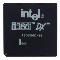
A80386DX16 Intel, A80386DX16 Datasheet - Page 11

A80386DX16
Manufacturer Part Number
A80386DX16
Description
IC MPU 32-BIT 5V 16MHZ 132-PGA
Manufacturer
Intel
Datasheet
1.A80386DX16.pdf
(139 pages)
Specifications of A80386DX16
Processor Type
386DX
Features
32-bit
Speed
16MHz
Voltage
5V
Mounting Type
Surface Mount
Package / Case
132-PGA
Family Name
Intel386 DX
Device Core Size
32b
Frequency (max)
16MHz
Supply Voltage 1 (typ)
5V
Operating Supply Voltage (max)
5.25V
Operating Supply Voltage (min)
4.75V
Operating Temp Range
0C to 85C
Operating Temperature Classification
Commercial
Mounting
Through Hole
Pin Count
132
Package Type
PGA
Lead Free Status / RoHS Status
Contains lead / RoHS non-compliant
Other names
807050
Available stocks
Company
Part Number
Manufacturer
Quantity
Price
OF
DF
IF
TF
SF
15
(Overflow Flag bit 11)
OF is set if the operation resulted in a signed
overflow Signed overflow occurs when the
operation resulted in carry borrow into the
sign bit (high-order bit) of the result but did
not result in a carry borrow out of the high-
order bit or vice-versa For 8 16 32 bit oper-
ations OF is set according to overflow at bit
7 15 31 respectively
(Direction Flag bit 10)
DF defines whether ESI and or EDI registers
postdecrement or postincrement during the
string instructions Postincrement occurs if
DF is reset Postdecrement occurs if DF is
set
(INTR Enable Flag bit 9)
The IF flag when set allows recognition of
external interrupts signalled on the INTR pin
When IF is reset external interrupts signalled
on the INTR are not recognized IOPL indi-
cates the maximum CPL value allowing alter-
ation of the IF bit when new values are
popped into EFLAGS or FLAGS
(Trap Enable Flag bit 8)
TF controls the generation of exception 1
trap when single-stepping through code
When TF is set the Intel386 DX generates an
exception 1 trap after the next instruction is
executed When TF is reset exception 1
traps occur only as a function of the break-
point addresses loaded into debug registers
DR0– DR3
(Sign Flag bit 7)
SF is set if the high-order bit of the result is
set it is reset otherwise For 8- 16- 32-bit
operations SF reflects the state of bit 7 15
31 respectively
REGISTERS
SEGMENT
Selector
Selector
Selector
Selector
Selector
Selector
Figure 2-4 Intel386
0
DS–
GS –
CS –
SS–
ES–
FS–
TM
Physical Base Address Segment Limit
DX Segment Registers and Associated Descriptor Registers
DESCRIPTOR REGISTERS (LOADED AUTOMATICALLY)
ZF
AF
PF
CF
Note in these descriptions ‘‘set’’ means ‘‘set to 1 ’’
and ‘‘reset’’ means ‘‘reset to 0 ’’
2 3 4 Segment Registers
Six 16-bit segment registers hold segment selector
values identifying the currently addressable memory
segments Segment registers are shown in Figure 2-
4 In Protected Mode each segment may range in
size from one byte up to the entire linear and physi-
(Zero Flag bit 6)
ZF is set if all bits of the result are 0 Other-
wise it is reset
(Auxiliary Carry Flag bit 4)
The Auxiliary Flag is used to simplify the addi-
tion and subtraction of packed BCD quanti-
ties AF is set if the operation resulted in a
carry out of bit 3 (addition) or a borrow into bit
3 (subtraction) Otherwise AF is reset AF is
affected by carry out of or borrow into bit 3
only regardless of overall operand length 8
16 or 32 bits
(Parity Flags bit 2)
PF is set if the low-order eight bits of the op-
eration contains an even number of ‘‘1’s’’
(even parity) PF is reset if the low-order eight
bits have odd parity PF is a function of only
the low-order eight bits regardless of oper-
and size
(Carry Flag bit 0)
CF is set if the operation resulted in a carry
out of (addition) or a borrow into (subtraction)
the high-order bit Otherwise CF is reset For
8- 16- or 32-bit operations CF is set accord-
ing to carry borrow at bit 7 15 or 31 respec-
tively
Intel386
Attributes from Descriptor
TM
DX MICROPROCESSOR
Segment
Other
11


