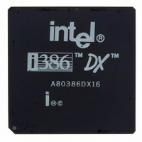
A80386DX16 Intel, A80386DX16 Datasheet - Page 87

A80386DX16
Manufacturer Part Number
A80386DX16
Description
IC MPU 32-BIT 5V 16MHZ 132-PGA
Manufacturer
Intel
Datasheet
1.A80386DX16.pdf
(139 pages)
Specifications of A80386DX16
Processor Type
386DX
Features
32-bit
Speed
16MHz
Voltage
5V
Mounting Type
Surface Mount
Package / Case
132-PGA
Family Name
Intel386 DX
Device Core Size
32b
Frequency (max)
16MHz
Supply Voltage 1 (typ)
5V
Operating Supply Voltage (max)
5.25V
Operating Supply Voltage (min)
4.75V
Operating Temp Range
0C to 85C
Operating Temperature Classification
Commercial
Mounting
Through Hole
Pin Count
132
Package Type
PGA
Lead Free Status / RoHS Status
Contains lead / RoHS non-compliant
Other names
807050
Available stocks
Company
Part Number
Manufacturer
Quantity
Price
- Current page: 87 of 139
- Download datasheet (2Mb)
Certain types of 16-bit or 8-bit operands require no
adjustment for correct transfer on a 16-bit bus
Those are read or write operands using only the low-
er half of the data bus and write operands using
only the upper half of the bus since the Intel386 DX
simultaneously duplicates the write data on the low-
er half of the data bus For these patterns of Byte
Enables and the R W
asserted at the Intel386 DX allowing NA
serted during the bus cycle if desired
5 4 4 Interrupt Acknowledge (INTA)
In response to an interrupt request on the INTR in-
put when interrupts are enabled the Intel386 DX
Interrupt Vector (0– 255) is read on D0– D7 at end of second Interrupt Acknowledge bus cycle
Because each Interrupt Acknowledge bus cycle is followed by idle bus states asserting NA
which is simplest for your system hardware design
Cycles
signals BS16
Figure 5-22 Interrupt Acknowledge Cycles
need not be
to be as-
performs two interrupt acknowledge cycles These
bus cycles are similar to read cycles in that bus defi-
nition signals define the type of bus activity taking
place and each cycle continues until acknowledged
by READY
The state of A2 distinguishes the first and second
interrupt acknowledge cycles The byte address
driven during the first interrupt acknowledge cycle is
4 (A31 – A3 low A2 high BE3 – BE1
BE0
interrupt acknowledge cycle is 0 (A31 – A2 low
BE3 – BE1
low) The address driven during the second
Intel386
sampled asserted
high BE0
has no practical effect Choose the approach
TM
DX MICROPROCESSOR
low)
231630 –26
high and
87
Related parts for A80386DX16
Image
Part Number
Description
Manufacturer
Datasheet
Request
R

Part Number:
Description:
Microprocessor: Intel Celeron M Processor 320 and Ultra Low Voltage Intel Celeron M Processor at 600MHz
Manufacturer:
Intel Corporation

Part Number:
Description:
Intel 82550 Fast Ethernet Multifunction PCI/CardBus Controller
Manufacturer:
Intel Corporation
Datasheet:

Part Number:
Description:
Intel StrataFlash memory 32 Mbit. Access speed 120 ns
Manufacturer:
Intel Corporation
Datasheet:

Part Number:
Description:
Intel StrataFlash memory 32 Mbit. Access speed 120 ns
Manufacturer:
Intel Corporation
Datasheet:

Part Number:
Description:
Intel StrataFlash memory 64 Mbit. Access speed 150 ns
Manufacturer:
Intel Corporation
Datasheet:

Part Number:
Description:
Intel StrataFlash memory 32 Mbit. Access speed 100 ns
Manufacturer:
Intel Corporation
Datasheet:

Part Number:
Description:
DA28F640J5A-1505 Volt Intel StrataFlash Memory
Manufacturer:
Intel Corporation
Datasheet:

Part Number:
Description:
5 Volt Intel StrataFlash?? Memory
Manufacturer:
Intel Corporation
Datasheet:

Part Number:
Description:
5 Volt Intel StrataFlash?? Memory
Manufacturer:
Intel Corporation

Part Number:
Description:
Intel 6300ESB I/O Controller Hub
Manufacturer:
Intel Corporation
Datasheet:

Part Number:
Description:
Intel 82801DB I/O Controller Hub (ICH4), Pb-Free SLI
Manufacturer:
Intel Corporation
Datasheet:

Part Number:
Description:
Intel 82801FB I/O Controller Hub (ICH6)
Manufacturer:
Intel Corporation
Datasheet:

Part Number:
Description:
Intel Strataflash Memory28F128J3 28F640J3 28F320J3
Manufacturer:
Intel Corporation
Datasheet:

Part Number:
Description:
Controllers, Intel 430TX PCIset: 82439TX System Controller (MTXC)
Manufacturer:
Intel Corporation


