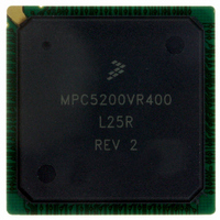
MPC5200VR400 Freescale Semiconductor, MPC5200VR400 Datasheet - Page 16

MPC5200VR400
Manufacturer Part Number
MPC5200VR400
Description
IC MPU 32BIT 400MHZ PPC 272-PBGA
Manufacturer
Freescale Semiconductor
Datasheet
1.MPC5200CVR400B.pdf
(80 pages)
Specifications of MPC5200VR400
Processor Type
MPC52xx PowerPC 32-Bit
Speed
400MHz
Voltage
1.5V
Mounting Type
Surface Mount
Package / Case
272-PBGA
Lead Free Status / RoHS Status
Lead free / RoHS Compliant
Features
-
Available stocks
Company
Part Number
Manufacturer
Quantity
Price
Company:
Part Number:
MPC5200VR400
Manufacturer:
Freescale Semiconductor
Quantity:
135
Company:
Part Number:
MPC5200VR400
Manufacturer:
FRRESCAL
Quantity:
838
Company:
Part Number:
MPC5200VR400
Manufacturer:
MOTOLOLA
Quantity:
648
Company:
Part Number:
MPC5200VR400
Manufacturer:
Freescale Semiconductor
Quantity:
10 000
Company:
Part Number:
MPC5200VR400B
Manufacturer:
TI
Quantity:
233
Company:
Part Number:
MPC5200VR400B
Manufacturer:
Freescale Semiconductor
Quantity:
10 000
Company:
Part Number:
MPC5200VR400BR2
Manufacturer:
Freescale Semiconductor
Quantity:
10 000
Electrical and Thermal Characteristics
3.3.3
The MPC5200 has three reset pins:
These signals are asynchronous I/O signals and can be asserted at any time. The input side uses a Schmitt
trigger and requires the same input characteristics as other MPC5200 inputs, as specified in the DC
Electrical Specifications section.
Notes:
1. For PORRESET the value of the minimum pulse width reflects the power on sequence. If PORRESET is asserted afterwards
2. The t
3. For t
4. For t
5. Following the deassertion of PORRESET, HRESET and SRESET remain low for 4096 reference clock cycles.
6. The deassertion of HRESET for at least the minimum pulse width forces the internal resets to be active for an additional 4096
16
its minimum pulse width equals the minimum given for HRESET related to the same reference clock.
clock cycles.
NOTES:
1
2
•
•
•
PORRESET
CAUTION—The SYS_XTAL_IN frequency and system PLL_CFG[0-6] settings must be chosen such that the
resulting system frequencies do not exceed their respective maximum or minimum operating frequencies. See the
MPC5200 User Manual [1].
SYS_XTAL_IN duty cycle is measured at V
lock,
up_osc,
t
HRESET
SRESET
VDD_stable
t
CYCLE
t
t
CV
Sym
CV
PORRESET - Power on Reset
HRESET - Hard Reset
SRESET - Software Reset
DUTY
Name
RISE
FALL
refer to the Oscillator/PLL section of this specification for further details.
IH
IL
Resets
refer to the Oscillator/PLL section of this specification for further details.
As long as VDD is not stable the HRESET output is not stable.
describes the time which is needed to get all power supplies stable.
SYS_XTAL_IN cycle time.
SYS_XTAL_IN rise time.
SYS_XTAL_IN fall time.
SYS_XTAL_IN duty cycle (measured at V
SYS_XTAL_IN input voltage high
SYS_XTAL_IN input voltage low
Power On Reset
Hardware Reset
Software Reset
Description
Table 14
t
VDD_stable
Table 13. SYS_XTAL_IN Timing
1
Description
Min Pulse Width
Table 14. Reset Pulse Width
4 clock cycles
4 clock cycles
MPC5200 Data Sheet, Rev. 4
M
specifies the pulse widths of the Reset inputs.
.
+t
up_osc
NOTE
M
+t
).
lock
2
Max Pulse
Width
—
—
—
28.6
40.0
Min
2.0
—
—
—
Reference Clock
SYS_XTAL_IN
SYS_XTAL_IN
SYS_XTAL_IN
Max
64.1
60.0
5.0
5.0
0.8
—
Freescale Semiconductor
Units
ns
ns
ns
%
V
V
SpecID
SpecID
A3.1
A3.2
A3.3
A2.1
A2.2
A2.3
A2.4
A2.5
A2.6


