MPC5200VR400 Freescale Semiconductor, MPC5200VR400 Datasheet - Page 9
MPC5200VR400
Manufacturer Part Number
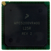
MPC5200VR400
Description
IC MPU 32BIT 400MHZ PPC 272-PBGA
Manufacturer
Freescale Semiconductor
Datasheet
1.MPC5200CVR400B.pdf
(80 pages)
Specifications of MPC5200VR400
Processor Type
MPC52xx PowerPC 32-Bit
Speed
400MHz
Voltage
1.5V
Mounting Type
Surface Mount
Package / Case
272-PBGA
Lead Free Status / RoHS Status
Lead free / RoHS Compliant
Features
-
Available stocks
Company
Part Number
Manufacturer
Quantity
Price
Company:

Part Number:
MPC5200VR400
Manufacturer:
Freescale Semiconductor
Quantity:
135
Company:
Part Number:
MPC5200VR400
Manufacturer:
FRRESCAL
Quantity:
838
Company:
Part Number:
MPC5200VR400
Manufacturer:
MOTOLOLA
Quantity:
648
Company:
Part Number:
MPC5200VR400
Manufacturer:
Freescale Semiconductor
Quantity:
10 000
Company:
Part Number:
MPC5200VR400B
Manufacturer:
TI
Quantity:
233
Company:
Part Number:
MPC5200VR400B
Manufacturer:
Freescale Semiconductor
Quantity:
10 000
Company:
Part Number:
MPC5200VR400BR2
Manufacturer:
Freescale Semiconductor
Quantity:
10 000


3.1.4
3.1.5
Power dissipation of the MPC5200 is caused by 3 different components: the dissipation of the internal or
core digital logic (supplied by VDD_CORE), the dissipation of the analog circuitry (supplied by
SYS_PLL_AVDD and CORE_PLL_AVDD) and the dissipation of the IO logic (supplied by
VDD_IO_MEM and VDD_IO).
figures for a range of operating modes. However, the dissipation due to the switching of the IO pins can
not be given in general, but must be calculated by the user for each application case using the following
formula
Freescale Semiconductor
V
V
Sym
V
I
I
CDM
HBM
LAT
LAT
MM
DRV8_OD
DRV16_MEM
DRV16_MEM
PCI
Driver Type
Electrostatic Discharge
Machine Model (MM)—JEDEC JESD22-A115
Charge Device Model (CDM)—JEDEC JESD22-C101
Latch-up Current at T
positive
negative
Latch-up Current at T
positive
negative
Power Dissipation
Human Body Model (HBM)—JEDEC JESD22-A114-B
This device contains circuitry that protects against damage due to
high-static voltage or electrical fields. However, it is advised that normal
precautions be taken to avoid application of any voltages higher than
maximum-rated voltages. Operational reliability is enhanced if unused
inputs are tied to an appropriate logic voltage level (i.e., either GND or
V
CC
).
Table 7
Table 4. Drive Capability of MPC5200 Output Pins (continued)
VDD_IO_MEM = 3.3V
VDD_IO_MEM = 2.5V
Table 5. ESD and Latch-Up Protection Characteristics
Supply Voltage
VDD_IO = 3.3V
VDD_IO = 3.3V
A
A
gives package thermal characteristics for this device.
=85
=27
Table 6
o
o
C
C
Rating
P IO
MPC5200 Data Sheet, Rev. 4
details typical measured core and analog power dissipation
=
P IOint
CAUTION
+
I
16
16
16
OH
-
∑
M
N
×
C
×
VDD_IO
Electrical and Thermal Characteristics
I
16
16
16
OL
2000
+100
+200
8
-100
-200
Min
200
500
2
×
f
Max
—
—
—
—
—
Unit
mA
mA
mA
mA
Unit
mA
mA
V
V
V
SpecID
D3.27
D3.28
D3.29
D3.30
SpecID
D4.1
D4.2
D4.3
D4.4
D4.5
9
Related parts for MPC5200VR400
Image
Part Number
Description
Manufacturer
Datasheet
Request
R

Part Number:
Description:
MPC5200 Quick Start
Manufacturer:
Freescale Semiconductor / Motorola
Datasheet:

Part Number:
Description:
Manufacturer:
Freescale Semiconductor, Inc
Datasheet:
Part Number:
Description:
Manufacturer:
Freescale Semiconductor, Inc
Datasheet:
Part Number:
Description:
Manufacturer:
Freescale Semiconductor, Inc
Datasheet:
Part Number:
Description:
Manufacturer:
Freescale Semiconductor, Inc
Datasheet:
Part Number:
Description:
Manufacturer:
Freescale Semiconductor, Inc
Datasheet:
Part Number:
Description:
Manufacturer:
Freescale Semiconductor, Inc
Datasheet:
Part Number:
Description:
Manufacturer:
Freescale Semiconductor, Inc
Datasheet:
Part Number:
Description:
Manufacturer:
Freescale Semiconductor, Inc
Datasheet:
Part Number:
Description:
Manufacturer:
Freescale Semiconductor, Inc
Datasheet:
Part Number:
Description:
Manufacturer:
Freescale Semiconductor, Inc
Datasheet:
Part Number:
Description:
Manufacturer:
Freescale Semiconductor, Inc
Datasheet:
Part Number:
Description:
Manufacturer:
Freescale Semiconductor, Inc
Datasheet:
Part Number:
Description:
Manufacturer:
Freescale Semiconductor, Inc
Datasheet:
Part Number:
Description:
Manufacturer:
Freescale Semiconductor, Inc
Datasheet: