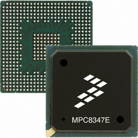
MPC8347EVVALFB Freescale Semiconductor, MPC8347EVVALFB Datasheet - Page 85

MPC8347EVVALFB
Manufacturer Part Number
MPC8347EVVALFB
Description
IC MPU POWERQUICC II 672-TBGA
Manufacturer
Freescale Semiconductor
Series
PowerQUICC II PROr
Specifications of MPC8347EVVALFB
Processor Type
MPC83xx PowerQUICC II Pro 32-Bit
Speed
667MHz
Voltage
1.3V
Mounting Type
Surface Mount
Package / Case
672-TBGA
Processor Series
MPC8xxx
Core
e300
Data Bus Width
32 bit
Development Tools By Supplier
MPC8349E-MITXE
Maximum Clock Frequency
667 MHz
Maximum Operating Temperature
+ 105 C
Mounting Style
SMD/SMT
I/o Voltage
1.8 V, 2.5 V, 3.3 V
Minimum Operating Temperature
0 C
Core Size
32 Bit
Program Memory Size
64KB
Cpu Speed
667MHz
Embedded Interface Type
I2C, SPI, USB, UART
Digital Ic Case Style
TBGA
No. Of Pins
672
Rohs Compliant
Yes
Family Name
MPC83xx
Device Core
PowerQUICC II Pro
Device Core Size
32b
Frequency (max)
667MHz
Instruction Set Architecture
RISC
Supply Voltage 1 (typ)
1.3V
Operating Supply Voltage (max)
1.36V
Operating Supply Voltage (min)
1.24V
Operating Temp Range
0C to 105C
Operating Temperature Classification
Commercial
Mounting
Surface Mount
Pin Count
672
Package Type
TBGA
Lead Free Status / RoHS Status
Lead free / RoHS Compliant
Features
-
Lead Free Status / Rohs Status
Lead free / RoHS Compliant
Available stocks
Company
Part Number
Manufacturer
Quantity
Price
Company:
Part Number:
MPC8347EVVALFB
Manufacturer:
Freescale Semiconductor
Quantity:
135
Company:
Part Number:
MPC8347EVVALFB
Manufacturer:
Freescale Semiconductor
Quantity:
10 000
Part Number:
MPC8347EVVALFB
Manufacturer:
FREESCALE
Quantity:
20 000
20.2
For the following sections, P
See
20.2.1
An estimation of the chip junction temperature, T
where:
The junction-to-ambient thermal resistance is an industry-standard value that provides a quick and easy
estimation of thermal performance. Generally, the value obtained on a single-layer board is appropriate for
a tightly packed printed-circuit board. The value obtained on the board with the internal planes is usually
appropriate if the board has low power dissipation and the components are well separated. Test cases have
demonstrated that errors of a factor of two (in the quantity T
20.2.2
The thermal performance of a device cannot be adequately predicted from the junction-to-ambient thermal
resistance. The thermal performance of any component is strongly dependent on the power dissipation of
surrounding components. In addition, the ambient temperature varies widely within the application. For
Freescale Semiconductor
Junction-to-case thermal
Junction-to-package natural convection on top
Notes
1. Junction temperature is a function of die size, on-chip power dissipation, package thermal resistance, mounting site (board)
2. Per SEMI G38-87 and JEDEC JESD51-2 with the single-layer board horizontal.
3. Per JEDEC JESD51-6 with the board horizontal.
4. Thermal resistance between the die and the printed-circuit board per JEDEC JESD51-8. Board temperature is measured on
5. Thermal resistance between the die and the case top surface as measured by the cold plate method (MIL SPEC-883 Method
6. Thermal characterization parameter indicating the temperature difference between package top and the junction temperature
temperature, ambient temperature, air flow, power dissipation of other components on the board, and board thermal
resistance.
the top surface of the board near the package.
1012.1).
per JEDEC JESD51-2. When Greek letters are not available, the thermal characterization parameter is written as Psi-JT.
Table 5
T
T
R
P
A
J
θ
D
Thermal Management Information
JA
= junction temperature (°C)
= ambient temperature for the package (°C)
= power dissipation in the package (W)
MPC8347E PowerQUICC™ II Pro Integrated Host Processor Hardware Specifications, Rev. 11
Estimation of Junction Temperature with Junction-to-Ambient
Thermal Resistance
Estimation of Junction Temperature with Junction-to-Board
Thermal Resistance
for I/O power dissipation values.
= junction-to-ambient thermal resistance (°C/W)
Table 62. Package Thermal Characteristics for PBGA (continued)
T
J
Characteristic
= T
D
A
= (V
+ (R
DD
θ
JA
× I
× P
DD
D
) + P
)
I/O
J
, can be obtained from the equation:
where P
I/O
J
– T
is the power dissipation of the I/O drivers.
A
) are possible.
Symbol
R
ψ
θJC
JT
Value
5
5
°C/W
°C/W
Unit
Notes
Thermal
5
6
85


