XPC8260CZUHFBC Freescale Semiconductor, XPC8260CZUHFBC Datasheet - Page 12
XPC8260CZUHFBC
Manufacturer Part Number
XPC8260CZUHFBC
Description
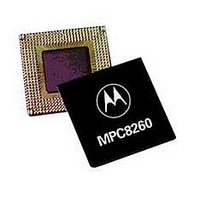
IC MPU POWERQUICC II 480-TBGA
Manufacturer
Freescale Semiconductor
Series
PowerQUICC IIr
Specifications of XPC8260CZUHFBC
Processor Type
MPC82xx PowerQUICC II 32-bit
Speed
166MHz
Voltage
2.5V
Mounting Type
Surface Mount
Package / Case
480-TBGA
Core Size
32 Bit
Program Memory Size
32KB
Cpu Speed
133MHz
Embedded Interface Type
I2C, MII, SPI, TDM, UTOPIA
Digital Ic Case Style
TBGA
No. Of Pins
480
Rohs Compliant
No
Family Name
MPC82XX
Device Core
PowerQUICC II
Device Core Size
32b
Frequency (max)
166MHz
Instruction Set Architecture
RISC
Supply Voltage 1 (typ)
1.8V
Operating Supply Voltage (max)
1.9V
Operating Supply Voltage (min)
1.7V
Operating Temp Range
-40C to 105C
Operating Temperature Classification
Industrial
Mounting
Surface Mount
Pin Count
480
Package Type
TBGA
Lead Free Status / RoHS Status
Contains lead / RoHS non-compliant
Features
-
Lead Free Status / Rohs Status
Not Compliant
Available stocks
Company
Part Number
Manufacturer
Quantity
Price
Company:

Part Number:
XPC8260CZUHFBC
Manufacturer:
Freescale Semiconductor
Quantity:
10 000


Electrical and Thermal Characteristics
2.2
Table 4
2.3
The average chip-junction temperature
where
For most applications P
T
Solving equations (1) and (2) for K gives:
12
J
is the following:
2
3
1
2
3
4
5
The leakage current is measured for nominal VDD, VCCSYN, and VDD.
MPC8265 and MPC8266 only.
Junction to ambient
Junction to board
Junction to case
MPC8260A PowerQUICC™ II Integrated Communications Processor Hardware Specifications, Rev. 2.0
T
T
θ
P
P
P
P
K = P
Assumes a single layer board with no thermal vias
Natural convection
Assumes a four layer board
Thermal resistance between the die and the printed circuit board per JEDEC JESD51-8. Board temperature is
measured on the top surface of the board near the package.
Thermal resistance between the die and the case top surface as measured by the cold plate method (MIL
SPEC-883 Method 1012.1).
describes thermal characteristics.
A
D
INT
I/O
D
JA
J
Thermal Characteristics
Power Considerations
= T
= ambient temperature °C
= P
= K/(T
= package thermal resistance
= power dissipation on input and output pins (determined by user)
= I
D
A
INT
DD
x (T
+ (P
Characteristics
J
+ P
x V
+ 273° C)
A
D
5
+ 273° C) +
I/O
x
4
DD
θ
I/O
JA
Watts (chip internal power)
Table 4. Thermal Characteristics for 480 TBGA Package
)
< 0.3 x P
θ
JA
x P
INT
,
junction to ambient
,
D
. If P
T
2
J
,
in °C can be obtained from the following:
Symbol
I/O
θ
θ
θ
JA
JB
JC
is neglected
,
°C/W
,
Value
an approximate relationship between P
13
10
11
1.1
8
4
3
1
1
3
°C/W
°C/W
°C/W
Unit
Freescale Semiconductor
Air Flow
1 m/s
1 m/s
NC
NC
—
—
2
(2)
(1)
(3)
D
and
Related parts for XPC8260CZUHFBC
Image
Part Number
Description
Manufacturer
Datasheet
Request
R

Part Number:
Description:
Manufacturer:
Freescale Semiconductor, Inc
Datasheet:
Part Number:
Description:
Manufacturer:
Freescale Semiconductor, Inc
Datasheet:
Part Number:
Description:
Manufacturer:
Freescale Semiconductor, Inc
Datasheet:
Part Number:
Description:
Manufacturer:
Freescale Semiconductor, Inc
Datasheet:
Part Number:
Description:
Manufacturer:
Freescale Semiconductor, Inc
Datasheet:
Part Number:
Description:
Manufacturer:
Freescale Semiconductor, Inc
Datasheet:
Part Number:
Description:
Manufacturer:
Freescale Semiconductor, Inc
Datasheet:
Part Number:
Description:
Manufacturer:
Freescale Semiconductor, Inc
Datasheet:
Part Number:
Description:
Manufacturer:
Freescale Semiconductor, Inc
Datasheet:
Part Number:
Description:
Manufacturer:
Freescale Semiconductor, Inc
Datasheet:
Part Number:
Description:
Manufacturer:
Freescale Semiconductor, Inc
Datasheet:
Part Number:
Description:
Manufacturer:
Freescale Semiconductor, Inc
Datasheet:
Part Number:
Description:
Manufacturer:
Freescale Semiconductor, Inc
Datasheet:
Part Number:
Description:
Manufacturer:
Freescale Semiconductor, Inc
Datasheet:
Part Number:
Description:
Manufacturer:
Freescale Semiconductor, Inc
Datasheet: