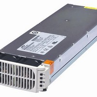
CP2000AC54TEP Lineage Power, CP2000AC54TEP Datasheet - Page 7

CP2000AC54TEP
Manufacturer Part Number
CP2000AC54TEP
Description
Linear & Switching Power Supplies 2000W +/-54Vdc 37A Rectifier POE
Manufacturer
Lineage Power
Datasheet
1.CP2000AC54TEP.pdf
(24 pages)
Specifications of CP2000AC54TEP
Product
Linear
Output Power Rating
2000 W
Input Voltage
176 VAC to 275 VAC
Number Of Outputs
1
Output Voltage (channel 1)
54 VDC
Mounting Style
Plug In
Dimensions
13.85 in L x 4 in W x 1.63 in H
Lead Free Status / Rohs Status
Lead free / RoHS Compliant
Alarm Table
10/10 Compact Power Line Brochure
Module Present Signal: This signal has dual functionality. It can
be used to alert the system when a module is inserted. A 500Ω
resistor is present in series between this signal and Logic_GRD. An
external pull-up should not raise the voltage on the pin above
0.25Vdc. Above 1Vdc, the write_protect feature of the EEPROM
isenabled.
Protocol Select: Establishes the communications mode of the
power supply. No connect for analog/I2C. For RS485, connect
10kΩ pull-down resistor to 54_OUT(-DC).
Enable: On/Off control when PMBus communications are utilized
as configured by the Protocol pin. This pin must be pulled low to
turn ON the power supply. The power supply will turn OFF if either
the Enable or the ON/OFF pin is released. The Enable function
does not exist for the RS485 protocol. This signal is referenced to
Logic_GRD.
ON/OFF: This is a short pin utilized for hot-plug applications to
ensure that the power supply turns OFF before the power pins are
disengaged. It also ensures that the power supply turns ON only
after the power pins have been engaged. Must be connected to
Vout ( - ).
1
2
3
4
This signal is correct if the rectifier is back biased from other rectifiers in the shelf .
Any detectable fault condition that does not result in the power supply shutting down. For example, ORing FET failure, boost section out of regulation, etc.
Signal transition from HI to LO is output load dependent
Signal must be pulled HI external to the module
Condition
OK
Thermal Alarm
(5C before shutdown)
Thermal Shutdown
Defective Fan
Blown AC Fuse in Unit
No AC <15mS (single unit)
AC Present but not within limits
AC not present
Boost Stage Failure
Over Voltage Latched Shutdown
Over Current
Non-catastrophic Internal Failure
1 Missing Module
Standby (remote)
Service Request (PMBus mode)
Communications Fault
(RS485 mode)
1
2
AC OK
Green
Blinks
1
1
1
1
1
0
0
1
1
1
1
1
1
1
Power Supply LED State
DC OK
Green
Blinks
1
1
0
0
0
1
0
0
0
0
1
0
1
1
© 2010 Lineage Power. All rights reserved.
Service
Amber
Blinks
0
1
1
0
0
0
0
0
0
0
0
0
0
0
Output Signals
Alert #: PMBus interrupt signal.
Fault: This signal goes LO for any failure that requires rectifier
replacement. Some of these faults may be due to:
• Fan failure
• Over-temperature condition
• Over-temperature shutdown
• Over-voltage shutdown
• Internal Rectifier Fault
Power Capacity: A HI on this pin indicates that the rectifier delivers
high power (2725W @ ≤240V, 2000W @ 277V) operation; a LO
indicates rectifier configured for 1200W operation.
Fault
Blinks
Red
0
0
1
1
1
0
0
0
1
1
0
1
0
0
T E C H N I C A L S P E C I FI C A T I ON S – R E C T I F I ER
Fault
LO
LO
LO
LO
LO
LO
HI
HI
HI
HI
HI
HI
HI
HI
HI
(Referenced to Logic_GRD)
Monitoring Signals
OTW
LO
LO
HI
HI
HI
HI
HI
HI
HI
HI
HI
HI
HI
HI
HI
PFW
LO
LO
LO
LO
LO
LO
LO
LO
LO
LO
HI
HI
HI
HI
HI
3
Module
Present
LO
LO
LO
LO
LO
LO
LO
LO
LO
LO
LO
LO
HI
LO
LO
LO
Page 7
4


