CP2000AC54TEP Lineage Power, CP2000AC54TEP Datasheet - Page 8
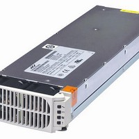
CP2000AC54TEP
Manufacturer Part Number
CP2000AC54TEP
Description
Linear & Switching Power Supplies 2000W +/-54Vdc 37A Rectifier POE
Manufacturer
Lineage Power
Datasheet
1.CP2000AC54TEP.pdf
(24 pages)
Specifications of CP2000AC54TEP
Product
Linear
Output Power Rating
2000 W
Input Voltage
176 VAC to 275 VAC
Number Of Outputs
1
Output Voltage (channel 1)
54 VDC
Mounting Style
Plug In
Dimensions
13.85 in L x 4 in W x 1.63 in H
Lead Free Status / Rohs Status
Lead free / RoHS Compliant


Output Connector
Mating Connector: AMP 1450572-1
10/10 Compact Power Line Brochure
Note: Connector is viewed from the rear positioned inside the rectifier
Signal pins columns 1 and 2 are referenced to V_OUT (–)
Signal pins columns 3 through 6 are referenced to Logic GRD
Signal Definitions
All hardware alarm signals (Fault, PFW, OTW, Power Capacity) are open drain FETs. These signals should be pulled HI to either 3.3V or
5V. Maximum sink current 5mA. An active LO signal (< 0.4Vdc) state. All signals are referenced to Logic GRD unless otherwise stated.
Contact your Lineage Power representative for more details.
C
Function
Output Enable
Power Fail Warning
I
Rectifier Fault
Module Present
ON/OFF
Protocol select
Margining
Over-Temperature Warning
Power Capacity
Rectifier address
Shelf Address
Back bias
Mux Reset
Standby power
Current Share
I
I
I
RS485 Line
A
D
B
2
2
2
2
C Interrupt
C Line 0
C Line 1
C Interrupt
SDA_0
SDA_1
SCL_0
SCL_1
6
MOD_PRES
Margin
OTW
Fault
5
Alert#_0
Label
Enable
PFW
Alert#_0
Alert#_1
Fault
MOD_PRES
ON/OFF
Protocol
Margin
OTW
POWER_CAP
Unit_addr
Shelf_addr
8V_INT
Reset
5VA
Ishare
SCL_0, SDA_0
SCL_1, SDA_1
Alert#
RS_485+
RS_485-
Enable
PFW
5VA
Signal Pins
4
LOGIC_GRD
Power_Cap
Alert#_1
A6
Reset
3
Type
Input
Output
Output
Output
Output
Input
Input
Input
Output
Output
Input
Input
Bi-direct
Input
Output
Bi-direct
Input
Input
Output
Bi-direct
A1
RS_485+
ON/OFF
RS_485-
Ishare
2
P7
Description
If shorted to LOGIC_GRD, the rectifier output is enabled when using I
May also be toggled to reset a latched OFF rectifier. Function not available in RS485 mode.
An open drain FET; normally HI, indicating output power is present. Changes to LO at least
5msec before the output voltage decays below 40Vdc.
Interrupt signal via I
signal pin is pulled up to 3.3V via a 10kΩ resistor and switches to active LO when an interrupt
occurs.
Indicates that an internal fault exists. An open drain FET; normally HI, changes to LO.
Short pin, see Status and Control description for further information on this signal.
Short pin, connects last and breaks first; used to activate and deactivate output during hot-
insertion and extraction, respectively. Ref: Vout ( - )
See Status and Control description for further information on this signal. Ref: Vout ( - ).
Allows changing of output voltage through an analog voltage input or via resistor divider.
An open drain FET; normally HI, changes to LO approximately 5°C prior to thermal shutdown.
Open drain FET; Used to indicate rectifier operation mode; HI indicates 2725W operation and
LO indicates 1200W operation.
Voltage level addressing of rectifiers within a single shelf. Ref: Vout ( - ).
Voltage level addressing of rectifiers within multiple shelves. Ref: Vout ( - ).
Diode OR’ed 8Vdc drain; used to back bias microprocessors and DSP of failed rectifier from
operating rectifiers. Ref: Vout ( - ).
Resets the I
5V at 0.75A provided for external use by either adjacent power supplies or the using system.
A single wire interface between each of the power unit forces them to share the load
current. Ref: Vout ( - ).
I
I
Goes active LO
RS485 line.
2
2
C line 0.
C line 1.
© 2010 Lineage Power. All rights reserved.
SHELF_ADDR
UNIT_ADDR
Protocol
8V_INT
2
1
C lines to I
2
C lines indicating that service is requested from the host controller. This
Last to make-first to break shortest pin
First make-last to break longest pin implemented in the mating connector
2
C line 0.
V_OUT
( - )
P7
T E C H N I C A L S P E C I FI C A T I ON S – R E C T I F I ER
V_OUT
Power Output
( + )
P8
P1
V_OUT
( + )
P6
V_OUT
( - )
P4
EARTH
(GND)
P3
2
C mode of operation.
Power Input
(Neutral)
LINE-2
P2
LINE-1
(HOT)
Page 8
P1
Related parts for CP2000AC54TEP
Image
Part Number
Description
Manufacturer
Datasheet
Request
R

Part Number:
Description:
Manufacturer:
Lineage Power
Datasheet: