HIN232CP Intersil, HIN232CP Datasheet - Page 20
HIN232CP
Manufacturer Part Number
HIN232CP
Description
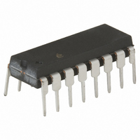
IC TXRX RS-232 5V 16-PDIP
Manufacturer
Intersil
Type
Transceiverr
Datasheet
1.HIN232CBZ.pdf
(21 pages)
Specifications of HIN232CP
Number Of Drivers/receivers
2/2
Protocol
RS232
Voltage - Supply
4.5 V ~ 5.5 V
Mounting Type
Through Hole
Package / Case
16-DIP (0.300", 7.62mm)
Lead Free Status / RoHS Status
Contains lead / RoHS non-compliant
Available stocks
Company
Part Number
Manufacturer
Quantity
Price
Company:

Part Number:
HIN232CP
Manufacturer:
INTERSIL
Quantity:
5 380
Company:
Part Number:
HIN232CP
Manufacturer:
INTERSIL
Quantity:
5 380
Company:
Part Number:
HIN232CP
Manufacturer:
Intersil
Quantity:
156
Part Number:
HIN232CP
Manufacturer:
INTERSIL
Quantity:
20 000
Part Number:
HIN232CPA
Manufacturer:
HIN
Quantity:
20 000
Company:
Part Number:
HIN232CPE
Manufacturer:
FREESCALE
Quantity:
13
Company:
Part Number:
HIN232CPZ
Manufacturer:
TI
Quantity:
2 500
Part Number:
HIN232CPZ
Manufacturer:
INTERSIL
Quantity:
20 000


Shrink Small Outline Plastic Packages (SSOP)
NOTES:
10. Controlling dimension: MILLIMETER. Converted inch dimensions
N
1
1. Symbols are defined in the “MO Series Symbol List” in Section 2.2
2. Dimensioning and tolerancing per ANSI Y14.5M-1982.
3. Dimension “D” does not include mold flash, protrusions or gate
4. Dimension “E” does not include interlead flash or protrusions.
5. The chamfer on the body is optional. If it is not present, a visual
6. “L” is the length of terminal for soldering to a substrate.
7. “N” is the number of terminal positions.
8. Terminal numbers are shown for reference only.
9. Dimension “B” does not include dambar protrusion. Allowable
0.25(0.010)
of Publication Number 95.
burrs. Mold flash, protrusion and gate burrs shall not exceed
0.20mm (0.0078 inch) per side.
Interlead flash and protrusions shall not exceed 0.20mm (0.0078
inch) per side.
index feature must be located within the crosshatched area.
dambar protrusion shall be 0.13mm (0.005 inch) total in excess of
“B” dimension at maximum material condition.
are not necessarily exact.
2
-A-
INDEX
AREA
3
e
B
D
M
C A
SEATING PLANE
M
E
-C-
HIN232, HIN236, HIN237, HIN238, HIN239, HIN240, HIN241
-B-
B S
A
20
H
A1
α
0.10(0.004)
0.25(0.010)
GAUGE
PLANE
0.010
A2
0.25
M
B
M
L
C
M28.209
28 LEAD SHRINK SMALL OUTLINE PLASTIC PACKAGE
SYMBOL
A1
A2
C
D
H
N
α
A
B
E
e
L
(JEDEC MO-150-AH ISSUE B)
0.002
0.065
0.009
0.004
0.390
0.197
0.292
0.022
MIN
0°
-
0.026 BSC
INCHES
28
0.078
0.072
0.014
0.009
0.413
0.220
0.322
0.037
MAX
8°
-
0.05
1.65
0.22
0.09
9.90
5.00
7.40
0.55
MILLIMETERS
MIN
0°
-
0.65 BSC
28
10.50
MAX
2.00
1.85
0.38
0.25
5.60
8.20
0.95
8°
-
September 26, 2008
Rev. 2 6/05
NOTES
FN3138.16
9
3
4
6
7
-
-
-
-
-
-
-
Related parts for HIN232CP
Image
Part Number
Description
Manufacturer
Datasheet
Request
R

Part Number:
Description:
+5V Powered RS-232 Transmitters/Receivers
Manufacturer:
Intersil Corporation
Datasheet:
Part Number:
Description:
Intersil Corporation [CMOS Serial Controller Interface]
Manufacturer:
Intersil Corporation
Datasheet:
Part Number:
Description:
Manufacturer:
Intersil Corporation
Datasheet:
Part Number:
Description:
357-036-542-201 CARDEDGE 36POS DL .156 BLK LOPRO
Manufacturer:
Intersil Corporation
Datasheet:
Part Number:
Description:
1024-Word x 4-Bit LSI Static RAM
Manufacturer:
Intersil Corporation
Datasheet:
Part Number:
Description:
General Purpose NPN Transistor Arrays FN341.4
Manufacturer:
Intersil Corporation
Datasheet:
Part Number:
Description:
CMOS 16-Bit Microprocessor
Manufacturer:
Intersil Corporation
Datasheet:
Part Number:
Description:
Manufacturer:
Intersil Corporation
Datasheet:
Part Number:
Description:
Manufacturer:
Intersil Corporation
Datasheet:
Part Number:
Description:
Manufacturer:
Intersil Corporation
Datasheet:
Part Number:
Description:
Manufacturer:
Intersil Corporation
Datasheet:
Part Number:
Description:
CMOS 6-Bit Latch and Decoder Memory Interfaces
Manufacturer:
Intersil Corporation
Datasheet:
Part Number:
Description:
CA3046General Purpose NPN Transistor Arrays
Manufacturer:
Intersil Corporation
Datasheet:
Part Number:
Description:
Manufacturer:
Intersil Corporation
Datasheet:
Part Number:
Description:
TR909 DLC/FLC SLIC with Low Power Standby
Manufacturer:
Intersil Corporation
Datasheet: