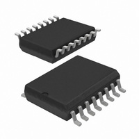
MC145406D,518 NXP Semiconductors, MC145406D,518 Datasheet - Page 5

MC145406D,518
Manufacturer Part Number
MC145406D,518
Description
IC DRIVER/RECEIVER TRIPLE 16SOIC
Manufacturer
NXP Semiconductors
Type
Transceiverr
Datasheet
1.MC145406N602.pdf
(5 pages)
Specifications of MC145406D,518
Number Of Drivers/receivers
3/3
Protocol
RS232
Voltage - Supply
4.5 V ~ 5.5 V
Mounting Type
Surface Mount
Package / Case
16-SOIC (0.300", 7.5mm Width)
Logic Family
MC145
Logic Type
Driver/Receiver
Maximum Operating Temperature
+ 70 C
Mounting Style
SMD/SMT
Interface
EIA/TIA- 232- D. V.28
Maximum Power Dissipation
1 W
Minimum Operating Temperature
0 C
Number Of Lines (input / Output)
6 / 6
Propagation Delay Time
500 ns
Lead Free Status / RoHS Status
Lead free / RoHS Compliant
Other names
568-1193-2
935024380518
MC145406D,623
MC145406D-T
935024380518
MC145406D,623
MC145406D-T
Philips Semiconductors Linear Products
APPLICATIONS INFORMATION
The MC145406 has been designed to meet the electrical
specifications of standards EIA-232-D/CCITT V.28 and as such,
August 31, 1994
EIA-232-D/V.28 driver/receiver
Figure 1. Power-Off Source Resistance (Drivers)
DRIVERS
RECEIVERS
DI
TX
RX
DO
DRIVERS
Figure 2. Switching Characteristics
Figure 3. Slew Rate Characteristics
1-3
1-3
1-3
1-3
TX
t
PHL
SLEW RATE (SR) =
14
12
10
1-3
t
90%
SLH
1
8
DI
DI
DI
V
V
DD
SS
1
2
3
–3V
90%
50%
50%
3V
t
50%
PHL
10%
V
9
TX
TX
TX
CC
16
1
2
3
t
10%
t
F
PLH
5
–3V –3V
3
7
t
t
SLH
F
R
t
OR
OUT
PLH
3V
–3V
t
3V – (–3V)
V
F
IN
=
t
t
SHL
SHL
t
F
= +2V
V
IN
I
V
V
V
V
3V
0V
+3V
0V
OH
OH
OL
OL
471
defines the electrical and physical interface between Data
Communication Equipment (DCE) and Data Terminal Equipment
(DTE). A DCE is connected to a DTE using a cable that typically
carries up to 25 leads, which allow the transfer of timing, data,
control, and test signals. The MC145406 provides the necessary
level shifting between the TTL/CMOS logic levels and the high
voltage levels of EIA-232-D (ranging from +3 to +25V).
DRIVERS
As defined by the specification, an EIA-232-D driver presents a
voltage of between +5 to +15V into a load of between 3 to 7k . A
logic one at the driver input results in a voltage of between -5 to
-15V. A logic zero results in a voltage between +5 to +15V. When
operating at +7 to +12V, the MC145406 meets this requirement.
When operating at +5V, the MC145406 drivers produce less than
+5V at the output (when terminated), which does not meet the
EIA-232-D specification. However, the output voltages when using
a +5V power supply are high enough (around +4V) to permit proper
reception by an EIA-232-D receiver, and can be used in applications
where strict compliance to EIA-232-D is not required.
Another requirement of the MC145406 drivers is that they withstand
a short to another driver in the EIA-232-D cable. The worst-case
condition that is permitted by EIA-232-D is a +15V source that is
current limited to 500mA. The MC145406 drivers can withstand this
condition momentarily. In most short circuit conditions the source
driver will have a series 300 output impedance needed to satisfy
the EIA-232-D driver requirements. This will reduce the short circuit
current to under 40mA which is an acceptable level for the
MC145406 to withstand.
Unlike some other drivers, the MC145406 drivers feature an
internally-limited output slew rate that does not exceed 30V/ s.
RECEIVERS
The job of an EIA-232-D receiver is to level-shift voltages in the
range of -25 to +25V down to TTL/CMOS logic levels (0 to +5V). A
voltage of between -3 and -25V on RX
produces a logic one at DO
space and produces a logic zero. While receiving these signals, the
RX inputs must present a resistance between 3 and 7k .
Nominally, the input resistance of the RX
The input threshold of the RX
above ground (GND) with typically 800mV of hysteresis included to
improve noise immunity. The 1.8V bias forces the appropriate DO
pin to a logic one when its RX input is open or grounded as called
for in EIA-232-D specification. Notice that TTL logic levels can be
applied to the RX inputs in lieu of normal EIA-232-D signal levels.
This might be helpful in situations where access to the modem or
computer through the EIA-232-D connector is necessary with TTL
devices. However, it is important not to connect the EIA-232-D
outputs (TX
may be damaged by the high output voltage of the MC145406.
The DO outputs are to be connected to a TTL or CMOS input (such
as an input to a modem chip). These outputs will swing from V
ground, allowing the designer to operate the DO and DI pins from
the digital power supply. The TX and RX sections are independently
powered by V
EIA-232-D signals at +12V.
1
) to TTL inputs since TTL operates off +5V only, and
DD
and V
SS
so that one may run logic at +5V and the
1
. A voltage between +3 and +25V is a
1-3
inputs is typically biased at 1.8V
1
is defined as a mark and
1-3
inputs is 5.0k .
MC145406
Product specification
CC
to


