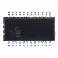
PCA9673DK,118 NXP Semiconductors, PCA9673DK,118 Datasheet - Page 14

PCA9673DK,118
Manufacturer Part Number
PCA9673DK,118
Description
IC I/O EXPANDER I2C 16B 24QSOP
Manufacturer
NXP Semiconductors
Datasheet
1.PCA9673PW112.pdf
(33 pages)
Specifications of PCA9673DK,118
Package / Case
24-QSOP
Interface
I²C
Number Of I /o
16
Interrupt Output
Yes
Frequency - Clock
1MHz
Voltage - Supply
2.3 V ~ 5.5 V
Operating Temperature
-40°C ~ 85°C
Mounting Type
Surface Mount
Includes
POR
Logic Family
PCA9673
Number Of Lines (input / Output)
16.0 / 16.0
Operating Supply Voltage
2.3 V to 5.5 V
Power Dissipation
600 mW
Operating Temperature Range
- 40 C to + 85 C
Input Voltage
5.5 V
Logic Type
I/O Expander
Maximum Clock Frequency
1 MHz
Mounting Style
SMD/SMT
Number Of Input Lines
16.0
Number Of Output Lines
16.0
Output Current
50 mA
Output Voltage
5.5 V
Lead Free Status / RoHS Status
Lead free / RoHS Compliant
Lead Free Status / RoHS Status
Lead free / RoHS Compliant, Lead free / RoHS Compliant
Other names
568-4198-2
935283557118
PCA9673DK-T
935283557118
PCA9673DK-T
NXP Semiconductors
PCA9673_1
Product data sheet
8.4 Power-on reset
8.5 Interrupt output (INT)
8.6 RESET input
When power is applied to V
a reset condition until V
and the PCA9673 registers and I
states. Thereafter V
The PCA9673 provides an open-drain interrupt (INT) which can be fed to a corresponding
input of the microcontroller (see
chips a kind of master function which can initiate an action elsewhere in the system.
An interrupt is generated by any rising or falling edge of the port inputs. After time t
signal INT is valid.
The interrupt disappears when data on the port is changed to the original setting or data is
read from or written to the device which has generated the interrupt.
In the write mode, the interrupt may become deactivated (HIGH) on the rising edge of the
write to port pulse. On the falling edge of the write to port pulse the interrupt is definitely
deactivated (HIGH).
The interrupt is reset in the read mode on the rising edge of the read from port pulse.
During the resetting of the interrupt itself, any changes on the I/Os may not generate an
interrupt. After the interrupt is reset any change in I/Os will be detected and transmitted as
an INT.
A reset can be accomplished by holding the RESET pin LOW for a minimum of t
PCA9673 registers and I
RESET input is once again HIGH.
Fig 19. Application of multiple PCA9673s with interrupt
MICROCOMPUTER
Remote 16-bit I/O expander for Fm+ I
DD
INT
Rev. 01 — 1 February 2007
must be lowered below 0.2 V to reset the device.
DD
2
C-bus state machine will be held in their default state until the
has reached V
DD
V
DD
, an internal Power-On Reset (POR) holds the PCA9673 in
Figure
2
C-bus/SMBus state machine will initialize to their default
PCA9673
device 1
INT
17,
POR
Figure
. At that point, the reset condition is released
PCA9673
device 2
18, and
INT
2
C-bus with interrupt and reset
Figure
19). This gives these
PCA9673
© NXP B.V. 2007. All rights reserved.
PCA9673
device 8
002aac308
INT
w(rst)
(v)D
14 of 33
. The
the


