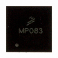
MPR083Q Freescale Semiconductor, MPR083Q Datasheet - Page 21

MPR083Q
Manufacturer Part Number
MPR083Q
Description
IC CTLR TOUCH SENSOR PROX 16-QFN
Manufacturer
Freescale Semiconductor
Type
Capacitiver
Datasheet
1.MPR083Q.pdf
(35 pages)
Specifications of MPR083Q
Number Of Inputs/keys
8 Slider
Data Interface
I²C, Serial
Voltage - Supply
1.8 V ~ 3.6 V
Current - Supply
1.62mA
Operating Temperature
-40°C ~ 85°C
Mounting Type
Surface Mount
Package / Case
16-QFN Exposed Pad
Output Type
Voltage
Interface
I²C
Input Type
Logic
Supply Voltage
3.3 V
Dimensions
5 mm L x 5 mm W x 1 mm H
Supply Current
41µA
Ic Interface Type
I2C
Supply Voltage Range
1.8V To 3.6V
Sensor Case Style
QFN
No. Of Pins
16
Operating Temperature Range
-40°C To +85°C
Filter Terminals
SMD
Rohs Compliant
Yes
For Use With
DEMOMPR083 - BOARD DEMO FOR MPR083 CTLRKITMPR083EVM - KIT EVAL 8POSITION ROTARY TOUCH
Lead Free Status / RoHS Status
Lead free / RoHS Compliant
Available stocks
Company
Part Number
Manufacturer
Quantity
Price
Company:
Part Number:
MPR083Q
Manufacturer:
Freescale
Quantity:
2 494
Sensors
Freescale Semiconductor
8
8.1
The MPR083 is self-calibrating. This is done both at initial start-up of the device and during run time.
8.2
Initial calibration of the MPR083 occurs every time the device resets. The first key detection cycle is used as a baseline
capacitance value for all remaining calculations. Thus, a touch is detected by taking the difference between this baseline value
and the current capacitance on the electrode.
8.3
The MPR083 has an auto-calibration feature. This is enabled through the Rotary Configuration Register
the ACE bit high. Auto calibration is done by two mechanisms. The basic auto-calibration will recalculate the baseline value after
6 sample periods. Thus the auto calibrate period can be calculate by multiplying the master clock period (in milliseconds) and the
touch acquisition sample period with a factor of 64.
If a touch is currently being detected the auto-calibration will not engage and calibration will be ignored. The device can also be
calibrated when a key is being touched, this is controlled by stuck key detection.
8.4
The Stuck Key Detection system allows the application to specify the maximum amount of time a touch should be detected before
it is calibrated into the baseline and the touch is ignored. This is controlled by setting the Stuck Key Timeout multiplication factor
(SKT). The timeout period can be calculated by multiplying the SKT, master clock period (in ms) and touch acquisition sample
period with a factor of 64.
When Stuck Key Detection is off a touched key will remain touched indefinitely and never be calibrated into the baseline value.
8.4.1 Stuck Key Timeout Register
The Stuck Key Timeout Register is used to determine the electrode scan period of the system. The I
Key Timeout Register is 0x09.
Table 15. Stuck Key Timeout Register Field Descriptions
Calibration
Introduction
Initial Start-up Conditions
Auto-Calibration
Stuck Key Detection
Reset:
AutoCalibrationPeriod ms
Field
SKT
7:0
W
R
AutoCalibrationPeriod ms
7
0
= Unimplemented
Stuck Key Timeout – The Stuck Key Timeout field selects or reports the
multiplication factor that is used to determine how often electrodes are calibrated
while a touch is being detected.
00000000 Encoding 0 – Turns off Stuck Key Detection
00000001 Encoding 1 – Sets the SKT multiplication factor to 2
~
11111111 Encoding 255 – Sets the SKT multiplication factor to 256
6
0
Figure 25. Stuck Key Timeout Register
5
0
=
MCP TASP SKT
=
4
0
MCP TASP
SKT
Description
3
0
2
0
64
64
2
1
0
C slave address of the Stuck
(Section
0
0
3.4), by setting
Equation 6
Equation 7
MPR083
21


