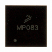
MPR083Q Freescale Semiconductor, MPR083Q Datasheet - Page 8

MPR083Q
Manufacturer Part Number
MPR083Q
Description
IC CTLR TOUCH SENSOR PROX 16-QFN
Manufacturer
Freescale Semiconductor
Type
Capacitiver
Datasheet
1.MPR083Q.pdf
(35 pages)
Specifications of MPR083Q
Number Of Inputs/keys
8 Slider
Data Interface
I²C, Serial
Voltage - Supply
1.8 V ~ 3.6 V
Current - Supply
1.62mA
Operating Temperature
-40°C ~ 85°C
Mounting Type
Surface Mount
Package / Case
16-QFN Exposed Pad
Output Type
Voltage
Interface
I²C
Input Type
Logic
Supply Voltage
3.3 V
Dimensions
5 mm L x 5 mm W x 1 mm H
Supply Current
41µA
Ic Interface Type
I2C
Supply Voltage Range
1.8V To 3.6V
Sensor Case Style
QFN
No. Of Pins
16
Operating Temperature Range
-40°C To +85°C
Filter Terminals
SMD
Rohs Compliant
Yes
For Use With
DEMOMPR083 - BOARD DEMO FOR MPR083 CTLRKITMPR083EVM - KIT EVAL 8POSITION ROTARY TOUCH
Lead Free Status / RoHS Status
Lead free / RoHS Compliant
Available stocks
Company
Part Number
Manufacturer
Quantity
Price
Company:
Part Number:
MPR083Q
Manufacturer:
Freescale
Quantity:
2 494
MPR083
8
When performing read-after-write verification, remember to re-set the command byte’s address because the stored command
byte address will generally have been auto-incremented after the write
2.3.8
The application should use repeated starts to address the MPR083 to avoid bus confusion between I
once a master issues a start/repeated start condition, that master owns the bus until a stop condition occurs. If a master that does
not own the bus attempts to take control of that bus, then improper addressing may occur. An address may always be rewritten
to fix this problem. Follow I
2.3.9
The RST is an active-low software reset. This is implemented in the Configuration Register by activating the RST bit. When
asserted, the device clears any transaction to or from the MPR083 on the serial interface and configures the internal registers to
the same state as a power-up reset
The sensor controller is capable of operating down to 1.8 V, however, in order for the sensor controller to exit reset and startup
correctly the host system must initially provide 2.0 V to 3.6 V input to V
is required in applications that require regulated operation in the 1.8 V to 2.0 V range. In the case that the application uses an
unregulated battery, then the battery must initially provide at least 2.0 V to correctly power-up the sensor controller which limits
battery selection to the 2.0 V to 3.6 V range.
S
Operation with Multiple Master
Device Reset
How command byte and data byte
acknowledge from MPR083
SLAVE ADDRESS
map into MPR083's registers
2
C protocol for multiple master configurations.
R/W
Figure 13. Low Voltage (1.8 V - 2.0 V) Power-up Sequence
(Table
1
A
4). The MPR083 then waits for a START condition on the serial interface.
D15 D14 D13 D12 D11 D10 D9 D8
Figure 12. ‘n’ Data Bytes Received
Lower V
DD
COMMAND BYTE
Established Comms with
Apply 2.0V to V
Is Data valid? (0 x 40)
To Sensor Controller
to the desired operating voltage
i.e. Read from FIFO
Sensor Controller?
Idle Delay Loop
1.8 V to 2.0 V
True
acknowledge from
DD
MPR083
DD
(Section
Max
and then follow the process in
False
A
2.4).
D7 D6
D5 D4
DATA BYTE
n bytes
acknowledge from
D3 D2
Freescale Semiconductor
2
C masters.On a I
Figure
auto-increment memory
MPR083
D1 D0
13. This process
word address
A
Sensors
2
C bus,
P


