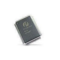
PI7C8140AMAE Pericom Semiconductor, PI7C8140AMAE Datasheet - Page 63

PI7C8140AMAE
Manufacturer Part Number
PI7C8140AMAE
Description
IC PCI-PCI BRIDGE 2PORT 128-QFP
Manufacturer
Pericom Semiconductor
Datasheet
1.PI7C8140AMAE.pdf
(82 pages)
Specifications of PI7C8140AMAE
Applications
*
Interface
*
Voltage - Supply
*
Package / Case
128-QFP
Mounting Type
Surface Mount
Maximum Operating Temperature
+ 85 C
Minimum Operating Temperature
0 C
Mounting Style
SMD/SMT
Operating Supply Voltage
3 V to 3.6 V
Supply Current (max)
230 mA
Lead Free Status / RoHS Status
Lead free / RoHS Compliant
Available stocks
Company
Part Number
Manufacturer
Quantity
Price
Company:
Part Number:
PI7C8140AMAE
Manufacturer:
Pericom
Quantity:
135
Company:
Part Number:
PI7C8140AMAE
Manufacturer:
SONY
Quantity:
469
Part Number:
PI7C8140AMAE
Manufacturer:
PERICOM
Quantity:
20 000
07-0067
13.2.11 SECONDARY BUS NUMBER REGISTER – OFFSET 18h
13.2.12 SUBORDINATE BUS NUMBER REGISTER – OFFSET 18h
13.2.13 SECONDARY LATENCY TIMER REGISTER – OFFSET 18h
13.2.14 I/O BASE ADDRESS REGISTER – OFFSET 1Ch
13.2.15 I/O LIMIT ADDRESS REGISTER – OFFSET 1Ch
Bit
15:8
Bit
23:16
Bit
31:24
Bit
3:0
7:4
Bit
11:8
Function
Secondary Bus
Number
Function
Subordinate
Bus Number
Function
Secondary
Latency Timer
Function
32-bit Indicator
I/O Base
Address [15:12]
Function
32-bit Indicator
Type
RW
Type
RW
Type
RW
Type
RO
RW
Type
RO
Description
Indicates the number of the PCI bus to which the secondary interface is
connected. The value is set in software during configuration.
Reset to 0
Description
Indicates the number of the PCI bus with the highest number that is subordinate to
the bridge. The value is set in software during configuration.
Reset to 0
Description
Latency timer for secondary. Indicates the number of PCI clocks from the
assertion of S_FRAME# to the expiration of the timer when the bridge is acting
as a master on the secondary.
0: Bridge ends the transaction after the first data transfer when the bridge’s
secondary bus grant has been deasserted, with the exception of memory write and
invalidate transactions.
Reset to 0
Description
Read as 01h to indicate 32-bit I/O addressing
Defines the bottom address of the I/O address range for the bridge to determine
when to forward I/O transactions from one interface to the other. The upper 4 bits
correspond to address bits [15:12] and are writable. The lower 12 bits
corresponding to address bits [11:0] are assumed to be 0. The upper 16 bits
corresponding to address bits [31:16] are defined in the I/O base address upper 16
bits address register
Reset to 0
Description
Read as 01h to indicate 32-bit I/O addressing
Page 63 of 82
2-PORT PCI-TO-PCI BRIDGE
March 20, 2007 – Revision 1.01
PI7C8140A


