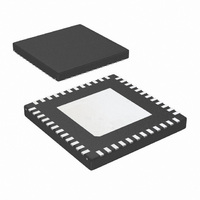
DS64EV400SQX/NOPB National Semiconductor, DS64EV400SQX/NOPB Datasheet - Page 5

DS64EV400SQX/NOPB
Manufacturer Part Number
DS64EV400SQX/NOPB
Description
IC EQUALIZER QUAD PROGR 48-LLP
Manufacturer
National Semiconductor
Series
PowerWise®r
Datasheet
1.DS64EV400SQNOPB.pdf
(18 pages)
Specifications of DS64EV400SQX/NOPB
Applications
Displays
Package / Case
48-LLP
Mounting Type
Surface Mount
For Use With
DS64EV400-EVK - BOARD EVAL 6.4GBPS QUAD EQUALIZR
Lead Free Status / RoHS Status
Lead free / RoHS Compliant
Voltage - Supply
-
Interface
-
Other names
DS64EV400SQX
CML RECEIVER INPUTS (IN_n+, IN_n-)
V
V
V
V
R
R
CML OUTPUTS (OUT_n+, OUT_n-)
V
V
t
R
R
t
t
t
t
EQUALIZATION
DJ1
DJ2
DJ3
DJ4
RJ
R
PLHD
PHLD
CCSK
PPSK
TX
INTRE
DDTX
ICMDC
OD
OCM
LI
IN
O
LO
, t
Symbol
F
Source Transmit Launch Signal
Level (IN diff)
Input Threshold Voltage
Supply Voltage of Transmitter to
EQ
Input Common Mode Voltage
Differential Input Return Loss
Input Resistance
Output Differential Voltage Level
(OUT diff)
Output Common Mode Voltage
Transition Time
Output Resistance
Differential Output Return Loss
Differential Low to High
Propagation Delay
Differential High to Low
Propagation Delay
Inter Pair Channel to Channel
Skew
Part to Part Output Skew
Residual Deterministic Jitter
at 10 Gbps
Residual Deterministic Jitter
at 6.4 Gbps
Residual Deterministic Jitter
at 5 Gbps
Residual Deterministic Jitter
at 2.5 Gbps
Random Jitter
Parameter
AC-Coupled or DC-Coupled
Requirement, Differential
measurement at point A.
Figure 1
Differential measurement at
point B. Figure 1
DC-Coupled Requirement
(Note 10)
DC-Coupled Requirement,
Differential measurement at point
A. Figure 1, (Note 7)
100 MHz – 3.2 GHz, with fixture’s
effect de-embedded
Differential across IN+ and IN-,
Figure 6.
Differential measurement with
OUT+ and OUT- terminated by
50Ω to GND, AC-Coupled
Figure 2
Single-ended measurement DC-
Coupled with 50Ω terminations
(Note 7)
20% to 80% of differential output
voltage, measured within 1” from
output pins. Figure 2, (Note 7)
Single ended to V
100 MHz – 1.6 GHz, with fixture’s
effect de-embedded. IN+ = static
high.
Propagation delay measurement
at 50% VO between input to
output, 100 Mbps. Figure 3,
(Note 7)
Difference in 50% crossing
between channels
Difference in 50% crossing
between outputs
30” of 6 mil microstrip FR4,
EQ Setting 0x06, PRBS-7 (2
pattern. (Note 6)
40” of 6 mil microstrip FR4,
EQ Setting 0x06, PRBS-7 (2
pattern. (Note 5, 6)
40” of 6 mil microstrip FR4,
EQ Setting 0x07, PRBS-7 (2
pattern. (Note 5, 6)
40” of 6 mil microstrip FR4,
EQ Setting 0x07, PRBS-7 (2
pattern. (Note 5, 6)
(Note 7, 8)
Conditions
5
DD
7
7
7
7
-1)
-1)
-1)
-1)
V
V
DD
DDTX
Min
400
500
1.6
0.8
85
20
42
– 0.2
–
(note 2)
0.20
0.17
0.12
Typ
120
100
620
240
240
0.1
0.5
10
50
10
20
7
V
V
DD
1600
DDTX
Max
0.26
0.20
0.16
V
115
725
0.2
60
58
– 0.1
DD
–
www.national.com
mV
mV
mV
psrms
Units
UI
UI
UI
UI
dB
dB
ps
ps
ps
ps
ps
Ω
Ω
V
V
V
P-P
P-P
P-P
P-P
P-P
P-P
P-P


