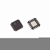
ISL8499IRZ Intersil, ISL8499IRZ Datasheet - Page 4

ISL8499IRZ
Manufacturer Part Number
ISL8499IRZ
Description
IC SWITCH QUAD SPDT 16QFN
Manufacturer
Intersil
Datasheet
1.ISL8499IRZ.pdf
(14 pages)
Specifications of ISL8499IRZ
Function
Switch
Circuit
4 x SPDT
On-state Resistance
250 mOhm
Voltage Supply Source
Single Supply
Voltage - Supply, Single/dual (±)
1.65 V ~ 4.5 V
Current - Supply
0.09µA
Operating Temperature
-40°C ~ 85°C
Mounting Type
Surface Mount
Package / Case
16-VQFN Exposed Pad, 16-HVQFN, 16-SQFN, 16-DHVQFN
Rohs Compliant
YES
Lead Free Status / RoHS Status
Lead free / RoHS Compliant
Available stocks
Company
Part Number
Manufacturer
Quantity
Price
Company:
Part Number:
ISL8499IRZ
Manufacturer:
INTERSIL
Quantity:
31 959
Company:
Part Number:
ISL8499IRZ-T
Manufacturer:
INTERSIL
Quantity:
24 000
Electrical Specifications - 4.3V Supply
NOTES:
Electrical Specifications - 3V Supply
10. Limits established by characterization and are not production tested.
11. r
Total Harmonic Distortion
NO or NC OFF Capacitance, C
COM ON Capacitance, C
POWER SUPPLY CHARACTERISTICS
Power Supply Range
Positive Supply Current, I+
Positive Supply Current, I+
DIGITAL INPUT CHARACTERISTICS
Input Voltage Low, V
Input Voltage High, V
Input Current, I
ANALOG SWITCH CHARACTERISTICS
Analog Signal Range, V
ON-Resistance, r
r
Δr
r
NO or NC OFF Leakage Current,
I
COM ON Leakage Current,
I
DYNAMIC CHARACTERISTICS
Turn-ON Time, t
Turn-OFF Time, t
Break-Before-Make Time Delay, t
6. V
7. The algebraic convention, whereby the most negative value is a minimum and the most positive a maximum, is used in this data sheet.
8. Parts are 100% tested at +25°C. Over-temperature limits established by characterization and are not production tested.
9. Flatness is defined as the difference between maximum and minimum value of ON-Resistance over the specified analog signal range.
NO(OFF)
COM(ON)
ON
ON
ON
value, between NC1 and NC2, NC3 and NC4 or between NO1 and NO2, NO3 and NO4.
ON
Matching Between Channels,
Flatness, r
IN
= input voltage to perform proper function.
matching between channels is calculated by subtracting the channel with the highest max r
or I
PARAMETER
PARAMETER
NC(OFF)
INH
FLAT(ON)
ON
ON
OFF
, I
INL
INL
INH
ANALOG
COM(ON)
OFF
D
4
f = 20Hz to 20kHz, V
f = 1MHz, V
f = 1MHz, V
V+ = +4.5V, V
V+ = +4.2V, V
V+ = 4.5V, V
V+ = 2.7V, I
(See Figure 5)
V+ = 2.7V, I
max r
V+ = 2.7V, I
(Note 9)
V+ = 3.3V, V
V+ = 3.3V, V
3V, or Floating
V+ = 2.7V, V
C
V+ = 2.7V, V
C
V+ = 3.3V, V
C
L
L
L
= 35pF, (See Figure 1, Note 10)
= 35pF, (See Figure 1, Note 10)
= 35pF, (See Figure 3, Note 10)
ON
, (Note 11)
COM
COM
COM
NO
NO
COM
COM
IN
NO
NO
NO
IN
IN
or V
or V
TEST CONDITIONS
TEST CONDITIONS
= 0V or V+, (Note 10)
or V
or V
or V
= 100mA, V
= 0V or V+
= 2.85V
= 100mA, V
= 100mA, V
= 0.3V, 3V, V
= 0.3V, 3V, or V
Unless Otherwise Specified (Continued)
Unless Otherwise Specified
Test Conditions: V+ = +3.9V to +4.5V, GND = 0V, V
Test Conditions: V+ = +2.7V to +3.3V, GND = 0V, V
NC
NC
NC
NC
NC
COM
= V
= V
= 1.5V, R
= 1.5V, R
= 1.5V, R
COM
COM
= 2V
NO
NO
NO
ISL8499
NO
PP
= 0V, (See Figure 7)
= 0V, (See Figure 7)
or V
or V
or V
NO
, R
L
L
L
or V
= 50Ω,
= 50Ω,
= 50Ω,
NC
NC
NC
or V
L
NC
= 600Ω
= Voltage at
= 0V to V+,
= 0V to V+,
NC
= 3V, 0.3V
= 0.3V,
TEMP
TEMP
(°C)
(°C)
Full
Full
Full
Full
Full
Full
Full
Full
Full
Full
Full
Full
Full
Full
25
25
25
25
25
25
25
25
25
25
25
25
ON
(Notes 7, 8)
(Notes 7, 8)
value from the channel with lowest max r
1.65
MIN
-0.5
MIN
1.6
0
2
-
-
-
-
-
-
-
-
-
-
-
-
-
-
-
-
-
-
-
-
-
INH
INH
= 1.6V, V
= 1.4V, V
0.003
TYP
TYP
0.04
0.06
106
212
0.3
1.2
13
35
21
17
1
3
-
-
-
-
-
-
-
-
-
-
-
-
-
INL
INL
= 0.5V (Note 6),
= 0.5V (Note 6),
(Notes 7, 8) UNITS
(Notes 7, 8) UNITS
MAX
MAX
0.09
0.45
0.08
0.09
0.15
0.15
4.5
1.4
0.5
0.5
0.6
V+
12
30
35
27
32
-
-
-
-
-
-
-
-
-
February 5, 2008
FN6111.3
μA
μA
μA
μA
pF
pF
nA
nA
nA
nA
ns
ns
ns
ns
ns
%
V
V
V
V
Ω
Ω
Ω
Ω
Ω
Ω
ON


