TEA1062A NXP Semiconductors, TEA1062A Datasheet - Page 6
TEA1062A
Manufacturer Part Number
TEA1062A
Description
Manufacturer
NXP Semiconductors
Datasheet
1.TEA1062A.pdf
(28 pages)
Specifications of TEA1062A
Primary Target Application
Telephone Sets
Operating Supply Voltage (typ)
2.7/3.4V
Max Transmitter Gain
53.5dB
Receiver Gain (max)
32.5dB
Operating Temp Range
-25C to 75C
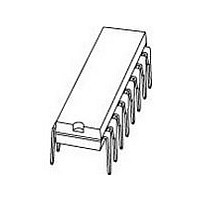
Package Type
PDIP
Pin Count
16
Operating Current
900uA
Operating Temperature Classification
Commercial
Mounting
Through Hole
Operating Supply Voltage (min)
2.2V
Lead Free Status / Rohs Status
Compliant
Available stocks
Company
Part Number
Manufacturer
Quantity
Price
Company:

Part Number:
TEA1062A
Manufacturer:
UTC
Quantity:
4 119
Company:
Part Number:
TEA1062A
Manufacturer:
PHILIPS
Quantity:
4 043
Part Number:
TEA1062A
Manufacturer:
PHILIPS/飞利浦
Quantity:
20 000
Company:
Part Number:
TEA1062A*
Manufacturer:
LITEON
Quantity:
1
Company:
Part Number:
TEA1062A/UTC1062A
Manufacturer:
INTEL
Quantity:
1
Part Number:
TEA1062AN
Manufacturer:
UTC/友顺
Quantity:
20 000
Part Number:
TEA1062AT
Manufacturer:
HP
Quantity:
20 000


Philips Semiconductors
Microphone inputs MIC+ and MIC and gain pins
GAS1 and GAS2
The circuit has symmetrical microphone inputs. Its input
impedance is 64 k (2
typically 52 dB (when R7 = 68 k , see Figures 14
and 15). Dynamic, magnetic, piezoelectric or electret (with
built-in FET source followers) can be used. Microphone
arrangements are illustrated in Fig.11.
The gain of the microphone amplifier can be adjusted
between 44 dB and 52 dB to suit the sensitivity of the
transducer in use. The gain is proportional to the value of
R7 which is connected between GAS1 and GAS2.
Stability is ensured by two external capacitors, C6
connected between GAS1 and SLPE and C8 connected
between GAS1 and V
may be increased to obtain a first-order low-pass filter.
The value of C8 is 10 times the value of C6. The cut-off
frequency corresponds to the time constant R7
Input MUTE (TEA1062)
When MUTE is HIGH the DTMF input is enabled and the
microphone and receiving amplifier inputs are inhibited.
The reverse is true when MUTE is LOW or open-circuit.
MUTE switching causes only negligible clicking on the line
and earpiece output. If the number of parallel sets in use
causes a drop in line current to below 6 mA the speech
amplifiers remain active independent to the DC level
applied to the MUTE input.
Input MUTE (TEA1062A)
When MUTE is LOW or open-circuit, the DTMF input is
enabled and the microphone and receiving amplifier inputs
are inhibited. The reverse is true when MUTE is HIGH.
MUTE switching causes only negligible clicking on the line
and earpiece output. If the number of parallel sets in use
causes a drop in line current to below 6 mA the DTMF
amplifier becomes active independent to the DC level
applied to the MUTE input.
Dual-tone multi-frequency input DTMF
When the DTMF input is enabled dialling tones may be
sent on to the line. The voltage gain from DTMF to LN is
typically 25.5 dB (when R7 = 68 k ) and varies with R7 in
the same way as the microphone gain. The signalling
tones can be heard in the earpiece at a low level
(confidence tone).
1997 Sep 03
Low voltage transmission circuits with
dialler interface
EE
. The value of C6 is 100 pF but this
32 k ) and its voltage gain is
C6.
6
Receiving amplifier IR, QR and GAR
The receiving amplifier has one input (IR) and a
non-inverting output (QR). Earpiece arrangements are
illustrated in Fig.12. The IR to QR gain is typically 31 dB
(when R4 = 100 k ). It can be adjusted between
20 and 31 dB to match the sensitivity of the transducer in
use. The gain is set with the value of R4 which is
connected between GAR and QR. The overall receive
gain, between LN and QR, is calculated by subtracting the
anti-sidetone network attenuation (32 dB) from the
amplifier gain. Two external capacitors, C4 and C7, ensure
stability. C4 is normally 100 pF and C7 is 10 times the
value of C4. The value of C4 may be increased to obtain a
first-order low-pass filter. The cut-off frequency will depend
on the time constant R4
The output voltage of the receiving amplifier is specified for
continuous-wave drive. The maximum output voltage will
be higher under speech conditions where the peak to RMS
ratio is higher.
Automatic Gain Control input AGC
Automatic line loss compensation is achieved by
connecting a resistor (R6) between AGC and V
The automatic gain control varies the gain of the
microphone amplifier and the receiving amplifier in
accordance with the DC line current. The control range is
5.8 dB which corresponds to a line length of 5 km for a
0.5 mm diameter twisted-pair copper cable with a DC
resistance of 176 /km and average attenuation of
1.2 dB/km). Resistor R6 should be chosen in accordance
with the exchange supply voltage and its feeding bridge
resistance (see Fig.13 and Table 1). The ratio of start and
stop currents of the AGC curve is independent of the value
of R6. If no automatic line-loss compensation is required
the AGC pin may be left open-circuit. The amplifiers, in this
condition, will give their maximum specified gain.
TEA1062; TEA1062A
C4.
Product specification
EE
.
Related parts for TEA1062A
Image
Part Number
Description
Manufacturer
Datasheet
Request
R

Part Number:
Description:
NXP Semiconductors designed the LPC2420/2460 microcontroller around a 16-bit/32-bitARM7TDMI-S CPU core with real-time debug interfaces that include both JTAG andembedded trace
Manufacturer:
NXP Semiconductors
Datasheet:

Part Number:
Description:
NXP Semiconductors designed the LPC2458 microcontroller around a 16-bit/32-bitARM7TDMI-S CPU core with real-time debug interfaces that include both JTAG andembedded trace
Manufacturer:
NXP Semiconductors
Datasheet:
Part Number:
Description:
NXP Semiconductors designed the LPC2468 microcontroller around a 16-bit/32-bitARM7TDMI-S CPU core with real-time debug interfaces that include both JTAG andembedded trace
Manufacturer:
NXP Semiconductors
Datasheet:
Part Number:
Description:
NXP Semiconductors designed the LPC2470 microcontroller, powered by theARM7TDMI-S core, to be a highly integrated microcontroller for a wide range ofapplications that require advanced communications and high quality graphic displays
Manufacturer:
NXP Semiconductors
Datasheet:
Part Number:
Description:
NXP Semiconductors designed the LPC2478 microcontroller, powered by theARM7TDMI-S core, to be a highly integrated microcontroller for a wide range ofapplications that require advanced communications and high quality graphic displays
Manufacturer:
NXP Semiconductors
Datasheet:
Part Number:
Description:
The Philips Semiconductors XA (eXtended Architecture) family of 16-bit single-chip microcontrollers is powerful enough to easily handle the requirements of high performance embedded applications, yet inexpensive enough to compete in the market for hi
Manufacturer:
NXP Semiconductors
Datasheet:
Part Number:
Description:
The XA-S3 device is a member of Philips Semiconductors? XA(eXtended Architecture) family of high performance 16-bitsingle-chip microcontrollers
Manufacturer:
NXP Semiconductors
Datasheet:

Part Number:
Description:
The NXP BlueStreak LH75401/LH75411 family consists of two low-cost 16/32-bit System-on-Chip (SoC) devices
Manufacturer:
NXP Semiconductors
Datasheet:
Part Number:
Description:
The NXP LPC3130/3131 combine an 180 MHz ARM926EJ-S CPU core, high-speed USB2
Manufacturer:
NXP Semiconductors
Datasheet:
Part Number:
Description:
The NXP LPC3141 combine a 270 MHz ARM926EJ-S CPU core, High-speed USB 2
Manufacturer:
NXP Semiconductors
Part Number:
Description:
The NXP LPC3143 combine a 270 MHz ARM926EJ-S CPU core, High-speed USB 2
Manufacturer:
NXP Semiconductors

Part Number:
Description:
The NXP LPC3152 combines an 180 MHz ARM926EJ-S CPU core, High-speed USB 2
Manufacturer:
NXP Semiconductors
Part Number:
Description:
The NXP LPC3154 combines an 180 MHz ARM926EJ-S CPU core, High-speed USB 2
Manufacturer:
NXP Semiconductors

Part Number:
Description:
Standard level N-channel enhancement mode Field-Effect Transistor (FET) in a plastic package using NXP High-Performance Automotive (HPA) TrenchMOS technology
Manufacturer:
NXP Semiconductors
Datasheet: