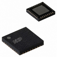
SC16C850SVIBS,151 NXP Semiconductors, SC16C850SVIBS,151 Datasheet - Page 33

SC16C850SVIBS,151
Manufacturer Part Number
SC16C850SVIBS,151
Description
IC UART SINGLE W/FIFO 32-HVQFN
Manufacturer
NXP Semiconductors
Datasheet
1.SC16C850SVIBS151.pdf
(48 pages)
Specifications of SC16C850SVIBS,151
Features
Programmable
Number Of Channels
1, UART
Fifo's
128 Byte
Protocol
RS485
Voltage - Supply
1.8V
With Auto Flow Control
Yes
With Irda Encoder/decoder
Yes
With False Start Bit Detection
Yes
With Modem Control
Yes
With Cmos
Yes
Mounting Type
Surface Mount
Package / Case
32-VFQFN Exposed Pad
Lead Free Status / RoHS Status
Lead free / RoHS Compliant
Other names
568-4707
935286785151
SC16C850SVIBS-S
935286785151
SC16C850SVIBS-S
NXP Semiconductors
SC16C850SV
Product data sheet
7.23 Advanced Feature Control Register 2 (AFCR2)
Table 32.
[1]
Table 33.
Bit
1
0
Bit
7:6
5
4
3
2
1
0
It takes 4 XTAL1 clocks to reset the device.
AFCR2[5]
AFCR2[4]
AFCR2[1]
Symbol
AFCR2[7:6]
AFCR2[3]
AFCR2[2]
AFCR2[0]
Symbol
AFCR1[1]
AFCR1[0]
Advanced Feature Control Register 1 bits description
Advanced Feature Control Register 2 bits description
Single UART with 128-byte FIFOs, IrDA, and XScale VLIO bus interface
All information provided in this document is subject to legal disclaimers.
SReset. Software reset. A write to this bit will reset the UART. Once the
RS485 RTS/DTR. Select RTS or DTR pin to control the external
RXDisable. Disable receiver.
9-bitMode. Enable 9-bit mode or Multidrop (RS-485) mode.
Description
UART is reset this bit is automatically set to logic 0.
TSR interrupt. Select TSR interrupt mode.
Description
reserved
RTSInvert. Invert RTS or DTR signal in auto 9-bit mode.
RTSCon. Enable the transmitter to control RTS or DTR signal in auto 9-bit
mode.
transceiver.
TXDisable. Disable transmitter.
logic 0 = transmit empty interrupt occurs when transmit FIFO falls below
the trigger level or becomes empty.
logic 1 = transmit empty interrupt occurs when transmit FIFO fall below
the trigger level, or becomes empty and the last stop bit has been shift
out the transmit shift register.
logic 0 = RTS or DTR is set to 0 by the UART during transmission, and to
1 during reception
logic 1 = RTS or DTR is set to 1 by the UART during transmission, and to
0 during reception
logic 0 = transmitter does not control RTS or DTR signal
logic 1 = transmitter controls RTS or DTR signal
logic 0 = RTS pin is used to control the external transceiver
logic 1 = DTR pin is used to control the external transceiver
logic 0 = transmitter is enabled
logic 1 = transmitter is disabled
logic 0 = receiver is enabled
logic 1 = receiver is disabled
logic 0 = normal RS-232 mode
logic 1 = enable 9-bit mode
Rev. 2 — 22 March 2011
SC16C850SV
…continued
[1]
© NXP B.V. 2011. All rights reserved.
33 of 48


