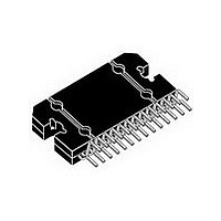
TDA7575B STMicroelectronics, TDA7575B Datasheet - Page 17

TDA7575B
Manufacturer Part Number
TDA7575B
Description
IC AMP DUAL BRIDGE FLEXIWATT27
Manufacturer
STMicroelectronics
Type
Class ABr
Datasheet
1.TDA7575BPDTR.pdf
(32 pages)
Specifications of TDA7575B
Output Type
1-Channel (Mono) or 2-Channel (Stereo)
Max Output Power X Channels @ Load
150W x 1 @ 1 Ohm; 75W x 2 @ 2 Ohm
Voltage - Supply
8 V ~ 18 V
Features
Differential Inputs, I²C, Mute, Short-Circuit and Thermal Protection, Standby
Mounting Type
Through Hole
Package / Case
27-Flexiwatt (bent and staggered leads)
Operational Class
Class-AB
Audio Amplifier Output Configuration
1-Channel Mono/2-Channel Stereo
Output Power (typ)
150x1@1Ohm/75x2@2OhmW
Audio Amplifier Function
Speaker
Input Offset Voltage
45@14.4VmV
Total Harmonic Distortion
0.02@4Ohm@30W%
Single Supply Voltage (typ)
9/12/15V
Dual Supply Voltage (typ)
Not RequiredV
Power Supply Requirement
Single
Power Dissipation
86W
Rail/rail I/o Type
No
Single Supply Voltage (min)
8V
Single Supply Voltage (max)
18V
Dual Supply Voltage (min)
Not RequiredV
Dual Supply Voltage (max)
Not RequiredV
Operating Temp Range
-55C to 150C
Operating Temperature Classification
Military
Mounting
Through Hole
Pin Count
27
Package Type
FLEXIWATT(Vertical)
Lead Free Status / RoHS Status
Lead free / RoHS Compliant
Available stocks
Company
Part Number
Manufacturer
Quantity
Price
Company:
Part Number:
TDA7575B BC
Manufacturer:
SMD
Quantity:
2
Part Number:
TDA7575B-BC
Manufacturer:
ST
Quantity:
20 000
Part Number:
TDA7575BBC
Manufacturer:
ST
Quantity:
20 000
Company:
Part Number:
TDA7575BPDTR
Manufacturer:
AMD
Quantity:
6 231
Part Number:
TDA7575BPDTR
Manufacturer:
ST
Quantity:
20 000
TDA7575B
5.5
Figure 27. Timing diagram on the I
Figure 28. Timing acknowledge clock pulse
1 Ω capability setting
It is possible to drive 1Ω load paralleling the outputs into a single channel.
In order to implement this feature, outputs are to be connected on the board as follows:
●
●
It is recommended to minimize the impedance on the board between OUT2 and the load in
order to minimize THD distortion. It is also recommended to control the maximum mismatch
impedance between V
pins (pin 24/pin 25 respect to pin 30/pin 31), mismatch that must not exceed a value of
20 mΩ.
With 1 Ω feature settled the active input is IN2 (pin 17 and pin 18), therefore IN1 pins should
be let floating.
It is possible to set the load capability acting on 1 Ω pin as follows:
It is to remember that 1
Ohm function is a hardware selection.
Therefore it is recommended to leave 1Ω pin floating or shorted to GND to set the two
channels mode configuration, or to short 1Ω pin to V
configuration.
OUT1+ (pin 35 and pin 36) shorted to OUT2+ (pin 19 and pin 20)
OUT1- (pin 28 and pin 29) shorted to OUT2- (pin 26 and pin 27).
1 Ω pin (pin 15) < 1.5 V: two channels mode (for a minimum load of 2 Ω)
1 Ω pin (pin 15) > 2.5 V: one channel mode (for 1 Ω load).
SCL
SDA
SDA
SCL
START
START
CC
pins (pin 21/pin 22 respect to pin 33/pin 34) and between PWGND
MSB
1
Doc ID 14103 Rev 2
2
2
C bus
D99AU1033
D99AU1032
3
CC
7
to set the one channel (1Ω)
8
ACKNOWLEDGMENT
FROM RECEIVER
STOP
9
I
2
I2C bus interface
CBUS
17/32


