TDA7563 STMicroelectronics, TDA7563 Datasheet - Page 14
TDA7563
Manufacturer Part Number
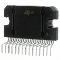
TDA7563
Description
IC AMP AUDIO 72W AB 27FLEXIWATT
Manufacturer
STMicroelectronics
Type
Class ABr
Datasheet
1.TDA7563.pdf
(20 pages)
Specifications of TDA7563
Output Type
4-Channel (Quad)
Max Output Power X Channels @ Load
72W x 4 @ 2 Ohm
Voltage - Supply
8 V ~ 18 V
Features
I²C, Mute, Short-Circuit and Thermal Protection, Standby
Mounting Type
Through Hole
Package / Case
27-Flexiwatt (bent and staggered leads)
Lead Free Status / RoHS Status
Contains lead / RoHS non-compliant
Other names
497-2183-5
Available stocks
Company
Part Number
Manufacturer
Quantity
Price

Part Number:
TDA7563
Manufacturer:
ST
Quantity:
20 000
Company:
Part Number:
TDA7563A
Manufacturer:
STMicroelectronics
Quantity:
135
Part Number:
TDA7563A
Manufacturer:
ST
Quantity:
20 000
Part Number:
TDA7563AEP
Manufacturer:
ST
Quantity:
20 000
Part Number:
TDA7563AH
Manufacturer:
ST
Quantity:
20 000
Part Number:
TDA7563B
Manufacturer:
ST
Quantity:
20 000


TDA7563
I
Data transmission from microprocessor to the TDA7563 and viceversa takes place through the 2 wires I
face, consisting of the two lines SDA and SCL (pull-up resistors to positive supply voltage must be connected).
Data Validity
As shown by fig. 22, the data on the SDA line must be stable during the high period of the clock. The HIGH and
LOW state of the data line can only change when the clock signal on the SCL line is LOW.
Start and Stop Conditions
As shown by fig. 23 a start condition is a HIGH to LOW transition of the SDA line while SCL is HIGH. The stop
condition is a LOW to HIGH transition of the SDA line while SCL is HIGH.
Byte Format
Every byte transferred to the SDA line must contain 8 bits. Each byte must be followed by an acknowledge bit.
The MSB is transferred first.
Acknowledge
The transmitter* puts a resistive HIGH level on the SDA line during the acknowledge clock pulse (see fig. 24).
The receiver** the acknowledges has to pull-down (LOW) the SDA line during the acknowledge clock pulse, so
that the SDAline is stable LOW during this clock pulse.
* Transmitter
** Receiver
Figure 22. Data Validity on the I
Figure 23. Timing Diagram on the I
Figure 24. Acknowledge on the I
14/20
2
C BUS INTERFACE
– master ( P) when it writes an address to the TDA7563
– slave (TDA7563) when the P reads a data byte from TDA7563
– slave (TDA7563) when the P writes an address to the TDA7563
– master ( P) when it reads a data byte from TDA7563
SDA
SCL
SDA
SCL
SDA
SCL
START
START
MSB
STABLE, DATA
1
2
DATA LINE
CBUS
2
VALID
CBUS
2
CBUS
2
D99AU1033
D99AU1032
ALLOWED
CHANGE
DATA
3
7
8
ACKNOWLEDGMENT
FROM RECEIVER
STOP
D99AU1031
I
2
CBUS
9
2
C BUS inter-
Related parts for TDA7563
Image
Part Number
Description
Manufacturer
Datasheet
Request
R

Part Number:
Description:
STMicroelectronics [RIPPLE-CARRY BINARY COUNTER/DIVIDERS]
Manufacturer:
STMicroelectronics
Datasheet:
Part Number:
Description:
STMicroelectronics [LIQUID-CRYSTAL DISPLAY DRIVERS]
Manufacturer:
STMicroelectronics
Datasheet:

Part Number:
Description:
BOARD EVAL FOR MEMS SENSORS
Manufacturer:
STMicroelectronics
Datasheet:
Part Number:
Description:
NPN TRANSISTOR POWER MODULE
Manufacturer:
STMicroelectronics
Datasheet:
Part Number:
Description:
TURBOSWITCH ULTRA-FAST HIGH VOLTAGE DIODE
Manufacturer:
STMicroelectronics
Datasheet:
Part Number:
Description:
Manufacturer:
STMicroelectronics
Datasheet:
Part Number:
Description:
DIODE / SCR MODULE
Manufacturer:
STMicroelectronics
Datasheet:
Part Number:
Description:
DIODE / SCR MODULE
Manufacturer:
STMicroelectronics
Datasheet:
Part Number:
Description:
Search -----> STE16N100
Manufacturer:
STMicroelectronics
Datasheet:
Part Number:
Description:
Search ---> STE53NA50
Manufacturer:
STMicroelectronics
Datasheet:
Part Number:
Description:
NPN Transistor Power Module
Manufacturer:
STMicroelectronics
Datasheet:
Part Number:
Description:
DIODE / SCR MODULE
Manufacturer:
STMicroelectronics
Datasheet: