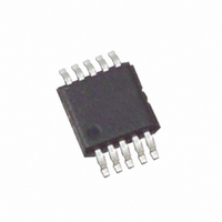
ISL59420IUZ-T7 Intersil, ISL59420IUZ-T7 Datasheet - Page 11

ISL59420IUZ-T7
Manufacturer Part Number
ISL59420IUZ-T7
Description
IC AMP MULTIPLEX 400MHZ 10-MSOP
Manufacturer
Intersil
Datasheet
1.ISL59420IUZ-T7.pdf
(12 pages)
Specifications of ISL59420IUZ-T7
Applications
2:1 Multiplexer-Amplifier
Number Of Circuits
1
-3db Bandwidth
420MHz
Slew Rate
1462 V/µs
Current - Supply
11mA
Current - Output / Channel
130mA
Mounting Type
Surface Mount
Package / Case
10-MSOP, Micro10™, 10-uMAX, 10-uSOP
Rohs Compliant
Yes
Lead Free Status / RoHS Status
Lead free / RoHS Compliant
Other names
ISL59420IUZ-T7
PC Board Layout
The frequency response of this circuit depends greatly on
the care taken in designing the PC board. The following are
recommendations to achieve optimum high frequency
performance from your PC board.
• The use of low inductance components such as chip
• Minimize signal trace lengths. Trace inductance and
• Match channel-channel analog I/O trace lengths and
• Maximize use of AC de-coupled PCB layers. All signal I/O
• Use proper value and location of termination resistors.
• When testing use good quality connectors and cables,
• Minimum of 2 power supply de-coupling capacitors are
resistors and chip capacitors is strongly recommended.
capacitance can easily limit circuit performance. Avoid
sharp corners, use rounded corners when possible. Vias
in the signal lines add inductance at high frequency and
should be avoided. PCB traces greater than 1" begin to
exhibit transmission line characteristics with signal rise/fall
times of 1ns or less. High frequency performance may be
degraded for traces greater than one inch, unless strip
lines are used.
layout symmetry. This will minimize propagation delay
mismatches.
lines should be routed over continuous ground planes (i.e.
no split planes or PCB gaps under these lines). Avoid vias
in the signal I/O lines.
Termination resistors should be as close to the device as
possible.
matching cable types and keeping cable lengths to a
minimum.
recommended (1000pF, 0.01µF) as close to the device as
possible. Avoid vias between the cap and the device
because vias add unwanted inductance. Larger caps can
be farther away. When vias are required in a layout, they
should be routed as far away from the device as possible.
11
ISL59420
September 22, 2005
FN7459.1


