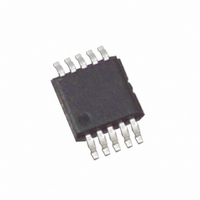
ISL59420IUZ-T7 Intersil, ISL59420IUZ-T7 Datasheet - Page 2

ISL59420IUZ-T7
Manufacturer Part Number
ISL59420IUZ-T7
Description
IC AMP MULTIPLEX 400MHZ 10-MSOP
Manufacturer
Intersil
Datasheet
1.ISL59420IUZ-T7.pdf
(12 pages)
Specifications of ISL59420IUZ-T7
Applications
2:1 Multiplexer-Amplifier
Number Of Circuits
1
-3db Bandwidth
420MHz
Slew Rate
1462 V/µs
Current - Supply
11mA
Current - Output / Channel
130mA
Mounting Type
Surface Mount
Package / Case
10-MSOP, Micro10™, 10-uMAX, 10-uSOP
Rohs Compliant
Yes
Lead Free Status / RoHS Status
Lead free / RoHS Compliant
Other names
ISL59420IUZ-T7
Absolute Maximum Ratings
Supply Voltage (V+ to V-). . . . . . . . . . . . . . . . . . . . . . . . . . . . . . . 11V
Input Voltage . . . . . . . . . . . . . . . . . . . . . . . . . . . . V- -0.5V, V+ +0.5V
Supply Turn-on Slew Rate . . . . . . . . . . . . . . . . . . . . . . . . . . . 1V/µs
IN- Input Current (Note 1) . . . . . . . . . . . . . . . . . . . . . . . . . . . . . 5mA
Digital & Analog Input Current (Note 1) . . . . . . . . . . . . . . . . . . 50mA
Output Current (Continuous) . . . . . . . . . . . . . . . . . . . . . . . . . . 50mA
ESD Rating
CAUTION: Stresses above those listed in “Absolute Maximum Ratings” may cause permanent damage to the device. This is a stress only rating and operation of the
device at these or any other conditions above those indicated in the operational sections of this specification is not implied.
NOTE:
IMPORTANT NOTE: All parameters having Min/Max specifications are guaranteed. Typical values are for information purposes only. Unless otherwise noted, all tests
are at the specified temperature and are pulsed tests, therefore: T
Electrical Specifications
GENERAL
±
I
V
I
V
Ib+
Ib-
R
R
A
I
LOGIC
V
V
I
I
AC GENERAL
- 3dB BW
1. If an input signal is applied before the supplies are powered up, the input current must be limited to these maximum values.
S
OUT
TRI
IH
IL
PARAMETER
Human Body Model (Per MIL-STD-883 Method 3015.7). . . . 2.5kV
Machine Model . . . . . . . . . . . . . . . . . . . . . . . . . . . . . . . . . . .300V
I
OUT
OS
out
IN
CL
H
L
S
Disabled
Enabled
or A
V
Supply Current
Disabled Supply Current I+
Disabled Supply Current I-
Positive Output Swing
Negative Output Swing
Output Current
Output Offset Voltage
Input Bias Current
Feedback Bias Current
Output Resistance
Input Resistance
Voltage Gain
Output Current in Three-state
Input High Voltage (Logic Inputs)
Input Low Voltage (Logic Inputs)
Input High Current (Logic Inputs)
Input Low Current (Logic Inputs)
-3dB Bandwidth
DESCRIPTION
2
V+ = +5V, V- = -5V, GND = 0V, T
(T
A
= 25°C)
J
= T
No load, V
No load, V
No load, V
V
V
R
V
HIZ = logic high, (DC), A
HIZ = logic low, (DC), A
V
R
V
A
C
A
C
C
V
V
IN
IN
IN
IN
OUT
L
F
L
L
= T
= 1, R
= 2, R
= 10Ω to GND
= R
= 5.5pF, C
= 5.5pF, C
= 2V, R
= -2V, R
= 0V
= 3.5V
ISL59420
A
= 0V
A
G
= 25°C, R
= 600Ω, V
F
F
IN
IN
IN
= 200Ω, V
= R
L
L
= 0V, ENABLE Low
= 0V, ENABLE High
= 0V, ENABLE High
= 500Ω, A
G
G
= 500Ω, A
G
CONDITIONS
= 0.6pF
= 0.6pF
Storage Temperature Range . . . . . . . . . . . . . . . . . .-65°C to +150°C
Ambient Operating Temperature . . . . . . . . . . . . . . . .-40°C to +85°C
Operating Junction Temperature . . . . . . . . . . . . . . .-40°C to +125°C
Power Dissipation . . . . . . . . . . . . . . . . . . . . . . . . . . . . . See Curves
θ
= 453Ω, V
JA
L
OUT
= 500Ω to GND unless otherwise specified.
. . . . . . . . . . . . . . . . . . . . . . . . . . . . . . . . . . . . . . . . . See Curves
OUT
V
V
V
= ±3V
V
= 2
= 1
= 2
= 400MV
= 1
OUT
= 2V
P-P
P-P
,
,
1.990
MIN
-12
-15
-20
-10
9.5
0.5
3.5
55
80
-4
2
2.005
TYP
130
-2.5
420
165
3.9
1.4
0.2
11
10
90
-3
1
3
4
7
6
0
2.020
MAX
-2.8
+12
-1.5
135
1.5
0.8
13
10
15
20
10
September 22, 2005
FN7459.1
UNIT
MHz
MHz
MΩ
MΩ
V/V
mA
mA
mA
mV
µA
µA
µA
µA
µA
µA
Ω
V
V
V
V


