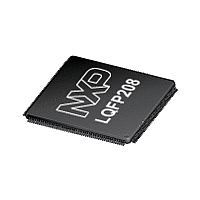
LPC1777FBD208 NXP Semiconductors, LPC1777FBD208 Datasheet - Page 11

LPC1777FBD208
Manufacturer Part Number
LPC1777FBD208
Description
The LPC1777 is a Cortex-M3 microcontroller for embedded applications featuring a high level of integration and low power consumption at frequencies of 120 MHz
Manufacturer
NXP Semiconductors
Datasheet
1.LPC1774FBD144.pdf
(120 pages)
Available stocks
Company
Part Number
Manufacturer
Quantity
Price
Company:
Part Number:
LPC1777FBD208
Manufacturer:
NXP
Quantity:
80 000
Company:
Part Number:
LPC1777FBD208,551
Manufacturer:
NXP Semiconductors
Quantity:
10 000
- Current page: 11 of 120
- Download datasheet (2Mb)
NXP Semiconductors
Table 3.
Not all functions are available on all parts. See
pins).
LPC178X_7X
Objective data sheet
Symbol
P0[5]
P0[6]
P0[7]
Pin description
166 C12
164 D13
162 C13
…continued
D11
B12
B11
115
113
112
[3]
[3]
[4]
All information provided in this document is subject to legal disclaimers.
I;
PU
I;
PU
I; IA I/O
Table 2
Rev. 3 — 27 December 2011
I/O
I/O
O
I
-
-
-
O
I/O
I/O
I/O
O
O
-
-
O
I/O
I/O
O
I
-
-
O
(Ethernet, USB, LCD, QEI, SD/MMC, DAC pins) and
Description
P0[5] — General purpose digital input/output pin.
I2S_RX_WS — I
master and received by the slave. Corresponds to the signal WS
in the I
CAN_TD2 — CAN2 transmitter output.
T2_CAP1 — Capture input for Timer 2, channel 1.
R — Function reserved.
R — Function reserved.
R — Function reserved.
LCD_VD[1] — LCD data.
P0[6] — General purpose digital input/output pin.
I2S_RX_SDA — I
and read by the receiver. Corresponds to the signal SD in the
I
SSP1_SSEL — Slave Select for SSP1.
T2_MAT0 — Match output for Timer 2, channel 0.
U1_RTS — Request to Send output for UART1. Can also be
configured to be an RS-485/EIA-485 output enable signal for
UART1.
R — Function reserved.
R — Function reserved.
LCD_VD[8] — LCD data.
P0[7] — General purpose digital input/output pin.
I2S_TX_SCK — I
and received by the slave. Corresponds to the signal SCK in the
I
SSP1_SCK — Serial Clock for SSP1.
T2_MAT1 — Match output for Timer 2, channel 1.
RTC_EV0 — Event input 0 to Event Monitor/Recorder.
R — Function reserved.
R — Function reserved.
LCD_VD[9] — LCD data.
2
2
S-bus specification.
S-bus specification.
2
S-bus specification.
2
2
S Receive word select. It is driven by the
2
S transmit clock. It is driven by the master
S Receive data. It is driven by the transmitter
32-bit ARM Cortex-M3 microcontroller
LPC178x/7x
© NXP B.V. 2011. All rights reserved.
Table 7
11 of 120
(EMC
Related parts for LPC1777FBD208
Image
Part Number
Description
Manufacturer
Datasheet
Request
R

Part Number:
Description:
32-bit ARM Cortex-M3 microcontroller; up to 512 kB flash
Manufacturer:
NXP [NXP Semiconductors]
Datasheet:
Part Number:
Description:
NXP Semiconductors designed the LPC2420/2460 microcontroller around a 16-bit/32-bitARM7TDMI-S CPU core with real-time debug interfaces that include both JTAG andembedded trace
Manufacturer:
NXP Semiconductors
Datasheet:

Part Number:
Description:
NXP Semiconductors designed the LPC2458 microcontroller around a 16-bit/32-bitARM7TDMI-S CPU core with real-time debug interfaces that include both JTAG andembedded trace
Manufacturer:
NXP Semiconductors
Datasheet:
Part Number:
Description:
NXP Semiconductors designed the LPC2468 microcontroller around a 16-bit/32-bitARM7TDMI-S CPU core with real-time debug interfaces that include both JTAG andembedded trace
Manufacturer:
NXP Semiconductors
Datasheet:
Part Number:
Description:
NXP Semiconductors designed the LPC2470 microcontroller, powered by theARM7TDMI-S core, to be a highly integrated microcontroller for a wide range ofapplications that require advanced communications and high quality graphic displays
Manufacturer:
NXP Semiconductors
Datasheet:
Part Number:
Description:
NXP Semiconductors designed the LPC2478 microcontroller, powered by theARM7TDMI-S core, to be a highly integrated microcontroller for a wide range ofapplications that require advanced communications and high quality graphic displays
Manufacturer:
NXP Semiconductors
Datasheet:
Part Number:
Description:
The Philips Semiconductors XA (eXtended Architecture) family of 16-bit single-chip microcontrollers is powerful enough to easily handle the requirements of high performance embedded applications, yet inexpensive enough to compete in the market for hi
Manufacturer:
NXP Semiconductors
Datasheet:
Part Number:
Description:
The XA-S3 device is a member of Philips Semiconductors? XA(eXtended Architecture) family of high performance 16-bitsingle-chip microcontrollers
Manufacturer:
NXP Semiconductors
Datasheet:

Part Number:
Description:
The NXP BlueStreak LH75401/LH75411 family consists of two low-cost 16/32-bit System-on-Chip (SoC) devices
Manufacturer:
NXP Semiconductors
Datasheet:

Part Number:
Description:
The NXP LPC3130/3131 combine an 180 MHz ARM926EJ-S CPU core, high-speed USB2
Manufacturer:
NXP Semiconductors
Datasheet:

Part Number:
Description:
The NXP LPC3141 combine a 270 MHz ARM926EJ-S CPU core, High-speed USB 2
Manufacturer:
NXP Semiconductors

Part Number:
Description:
The NXP LPC3143 combine a 270 MHz ARM926EJ-S CPU core, High-speed USB 2
Manufacturer:
NXP Semiconductors

Part Number:
Description:
The NXP LPC3152 combines an 180 MHz ARM926EJ-S CPU core, High-speed USB 2
Manufacturer:
NXP Semiconductors

Part Number:
Description:
The NXP LPC3154 combines an 180 MHz ARM926EJ-S CPU core, High-speed USB 2
Manufacturer:
NXP Semiconductors


