LPC2157_2158 NXP Semiconductors, LPC2157_2158 Datasheet - Page 5

LPC2157_2158
Manufacturer Part Number
LPC2157_2158
Description
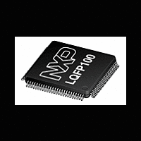
The LPC2157/2158 is a multi-chip module consisting of a LPC2138/2148 single-chipmicrocontroller combined with a PCF8576D Universal LCD driver in a low-cost 100-pinpackage
Manufacturer
NXP Semiconductors
Datasheet
1.LPC2157_2158.pdf
(45 pages)
NXP Semiconductors
Table 2.
LPC2157_2158_2
Product data sheet
Symbol
P0[0] to P0[31]
P0[0]/TXD0/
PWM1
P0[1]/RXD0/
PWM3/EINT0
P0[2]/SCL0/
CAP0[0]
P0[3]/SDA0/
MAT0[0]/EINT1
P0[4]/SCK0/
CAP0[1]/AD0[6]
P0[5]/MISO0/
MAT0[1]/AD0[7]
Pin description LPC2157
5.2 Pin description
Pin
7
9
10
14
15
17
[1]
[2]
[3]
[3]
[4]
[4]
Fig 5.
Type
I/O
I/O
O
O
I/O
I
O
I
I/O
I/O
I
I/O
I/O
O
I
I/O
I/O
I
I
I/O
I/O
O
I
Pin configuration for LPC2158
Description
Port 0: Port 0 is a 32-bit I/O port with individual direction controls for each bit.
Total of 31 pins of the Port 0 can be used as a general purpose bidirectional
digital I/Os while P0[31] is output only pin. The operation of port 0 pins
depends upon the pin function selected via the pin connect block.
Pin P0[24] is not available.
P0[0] — General purpose input/output digital pin (GPIO).
TXD0 — Transmitter output for UART0.
PWM1 — Pulse Width Modulator output 1.
P0[1] — General purpose input/output digital pin (GPIO).
RXD0 — Receiver input for UART0.
PWM3 — Pulse Width Modulator output 3.
EINT0 — External interrupt 0 input.
P0[2] — General purpose input/output digital pin (GPIO).
SCL0 — I
CAP0[0] — Capture input for Timer 0, channel 0.
P0[3] — General purpose input/output digital pin (GPIO).
SDA0 — I
MAT0[0] — Match output for Timer 0, channel 0.
EINT1 — External interrupt 1 input.
P0[4] — General purpose input/output digital pin (GPIO).
SCK0 — Serial clock for SPI0. SPI clock output from master or input to slave.
CAP0[1] — Capture input for Timer 0, channel 1.
AD0[6] — ADC 0, input 6.
P0[5] — General purpose input/output digital pin (GPIO).
MISO0 — Master In Slave Out for SPI0. Data input to SPI master or data
output from SPI slave.
MAT0[1] — Match output for Timer 0, channel 1.
AD0[7] — ADC 0, input 7.
Rev. 02 — 9 February 2009
2
2
C0 clock input/output. Open-drain output (for I
C0 data input/output. Open-drain output (for I
25
1
LPC2158FBD
Single-chip 16-bit/32-bit microcontrollers
002aad444
75
51
LPC2157/2158
2
2
C-bus compliance).
C-bus compliance).
© NXP B.V. 2009. All rights reserved.
5 of 45


