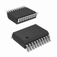
ISL24011IVZ-T Intersil, ISL24011IVZ-T Datasheet - Page 3

ISL24011IVZ-T
Manufacturer Part Number
ISL24011IVZ-T
Description
IC DRIVER TFT/LCD HV 20-TSSOP
Manufacturer
Intersil
Datasheet
1.ISL24011IVZ.pdf
(9 pages)
Specifications of ISL24011IVZ-T
Logic Function
Level Shifter
Number Of Bits
8
Input Type
Voltage
Output Type
Voltage
Number Of Channels
1
Number Of Outputs/channel
8
Differential - Input:output
No/No
Propagation Delay (max)
260ns
Operating Temperature
-40°C ~ 85°C
Package / Case
20-TSSOP
Lead Free Status / RoHS Status
Lead free / RoHS Compliant
Supply Voltage
-
Voltage - Supply
-
Data Rate
-
Absolute Maximum Ratings
Driver Positive Supply Voltage Range, (V
Power Supply Voltage Range, (V
Negative Supply Voltage Range, (V
Supply Turn-On Slew Rate . . . . . . . . . . . . . . . . . . . . . . . . . . 10V/µs
Input Voltage Range, All Inputs . . . . . . . . . . . . . . . . . . -0.5V to 5.5V
Output Voltage Range, All Outputs . . . . . V
ESD
CAUTION: Stresses above those listed in “Absolute Maximum Ratings” may cause permanent damage to the device. This is a stress only rating and operation of the
device at these or any other conditions above those indicated in the operational sections of this specification is not implied.
NOTE:
IMPORTANT NOTE: All parameters having Min/Max specifications are guaranteed. Typical values are for information purposes only. Unless otherwise noted, all tests
are at the specified temperature and are pulsed tests, therefore: T
Electrical Specifications
Power Supplies Recommended Operating Voltages
1. θ
PARAMETER
HBM . . . . . . . . . . . . . . . . . . . . . . . . . . . . . . . . . . . . . . . . . . . . .6kV
MM . . . . . . . . . . . . . . . . . . . . . . . . . . . . . . . . . . . . . . . . . . . . .300V
CDM . . . . . . . . . . . . . . . . . . . . . . . . . . . . . . . . . . . . . . . . . . . . .1kV
I(V
JA
I(V
VOH
VOL
VIH
tplh
tphl
VIL
ttlh
tthl
I
OFF
IN
ON
is measured with the component mounted on a HIGH effective thermal conductivity test board in free air. See Tech Brief TB379 for details.
)
)
Supply Current
Supply Current
Input Leakage
High Level Output Voltage IOH = -100µA
Low Level Output Voltage
High Level Input Voltage
Low Level Input Voltage
Low to High Prop Delay
High to Low Prop Delay
Rise Time
Fall Time
DESCRIPTION
ON
3
OFF
V
to V
ON
(T
) . . . . . . . . . . . . . -20V to -5V
A
OFF
ON
= 22V, V
= 25°C)
OFF
) . . . . . . . . +5V to +40V
). . . . . . . +10V to +60V
All Inputs low or high
No load
V
All Inputs low or high
No load
Each Input low or high
High = 1.8V, Low = 0.8V
V
RL = 4700pF in parallel with 5kΩ
IOH = +100µA
V
RL = 4700pF in parallel with 5kΩ
50% to 50%, Tested with
RL = 4700pF in parallel with 5kΩ,
f = 50kHz
Measured at 50% to 50%
f = 50kHz
RL = 4700pF in parallel with 5kΩ
Measured at 10% to 90%
f = 50kHz
RL = 4700pF in parallel with 5kΩ
Measured at 10% to 90%
f = 50kHz
RL = 4700pF in parallel with 5kΩ
-0.5V to V
ON
ON
OFF
OFF
= V
= 22V
= -5V
= -5V, T
ON1
J
ON
= T
CONDITION
+ V
+0.5V
C
A
ON2
= T
= -40°C to +85°C Unless Otherwise Specified. Typical values tested at 25°C
ISL24011
A
Thermal Information
Thermal Resistance (Typical, Note 1)
I
T
T
T
OUT
AMBIENT
JUNCTION
STORAGE
20 Ld TSSOP Package . . . . . . . . . . . . . . . . . . . . . .
(continuous, all 8 channels) . . . . . . . . . . . . . . . . . . . . . . 80mA
(V
. . . . . . . . . . . . . . . . . . . . . . . . . . . . . . . . .-40°C to +85°C
. . . . . . . . . . . . . . . . . . . . . . . . . . . . . . . .-65°C to +150°C
ON
(V
. . . . . . . . . . . . . . . . . . . . . . . . . . . . . . .-40°C to +150°C
MIN
-8.0
-10
1.8
OFF
-5
- 1.5V)
)
±
TYP
21.2
-5.0
-4.3
190
230
260
290
5.0
3.5
(V
OFF
(V
MAX
400
400
400
500
8.0
0.8
22
10
ON
+ 1.5V)
)
March 28, 2006
θ
JA
UNIT
mA
mA
µA
ns
ns
ns
ns
V
V
V
V
V
140
FN6196.2
(°C/W)


