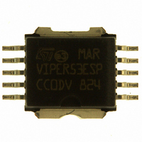
VIPER53ESPTR-E STMicroelectronics, VIPER53ESPTR-E Datasheet - Page 13

VIPER53ESPTR-E
Manufacturer Part Number
VIPER53ESPTR-E
Description
IC OFFLINE SWIT PWM POWERSO10
Manufacturer
STMicroelectronics
Series
VIPER™r
Datasheet
1.VIPER53ESPTR-E.pdf
(31 pages)
Specifications of VIPER53ESPTR-E
Output Isolation
Isolated
Frequency Range
93 ~ 300kHz
Voltage - Input
8.4 ~ 19 V
Voltage - Output
620V
Power (watts)
40W
Operating Temperature
25°C ~ 125°C
Package / Case
PowerSO-10 Exposed Bottom Pad
On Resistance (max)
1.7 Ohms
Supply Voltage (max)
19 V
Supply Voltage (min)
2.6 V
Maximum Operating Temperature
+ 150 C
Minimum Operating Temperature
- 40 C
Mounting Style
SMD/SMT
Number Of Switches
Single
Off Isolation (typ)
8.4 V
Operating Temperature (max)
150C
Operating Temperature (min)
-40C
Pin Count
10
Mounting
Surface Mount
Package Type
PowerSO
Screening Level
Automotive
For Use With
497-8435 - BOARD EVAL FOR VIPER53 28W497-6458 - BOARD EVAL BASED ON VIPER53-E497-6262 - BOARD REF SGL VIPER53 90-264VAC497-5866 - EVAL BOARD 24W NEG OUT VIPER53E497-5865 - EVAL BOARD 24W POS OUT VIPER53E497-4933 - BOARD PWR SUPPLY 24W OUTPUT VIPE
Lead Free Status / RoHS Status
Lead free / RoHS Compliant
Other names
497-5772-2
Available stocks
Company
Part Number
Manufacturer
Quantity
Price
Company:
Part Number:
VIPER53ESPTR-E
Manufacturer:
TI
Quantity:
1 500
Part Number:
VIPER53ESPTR-E
Manufacturer:
ST
Quantity:
20 000
VIPer53EDIP - E / VIPer53ESP - E
8
High Voltage Start-up Current Source
An integrated high voltage current source provides a bias current from the DRAIN pin during
the start-up phase. This current is partially absorbed by internal control circuits in standby
mode with reduced consumption, and also supplies the external capacitor connected to the
V
UVLO logic, the device turns into active mode and starts switching. The start-up current
generator is switched off, and the converter should normally provide the needed current on
the V
page
The external capacitor C
the converter to start-up, when the device starts switching. This time tss depends on many
parameters, including transformer design, output capacitors, soft start feature, and
compensation network implemented on the COMP pin and possible secondary feedback
circuit. The following formula can be used for defining the minimum capacitor needed:
Figure 9 on page 22
current I
down to I
rise. Device starts switching for V
energy to V
The charging current change at V
maintains a low restart duty cycle. This is especially useful for short circuits and overloads
conditions, as described in the following section.
DD
pin. As soon as the voltage on this pin reaches the high voltage threshold V
DD
8.
DDch1
pin through the auxiliary winding of the transformer, as shown on
DDch2
DD
at about 9 mA. When about V
capacitor after the start-up time tss.
which is about 0.6mA. This lower current leads to a slope change on the V
shows a typical start-up event. V
VDD
on the V
DD
DDoff
DocRev1
equal to V
DD
C
allows a fast complete start-up time t
VD D
pin must be sized according to the time needed by
DDoff
I
------------------------
V
D D1
DDon
DDhyst
is reached, the charging current is reduced
tss
, and the auxiliary winding delivers some
High Voltage Start-up Current Source
DD
starts from 0V with a charging
Figure 3 on
SDU
, and
DDon
of the
13/31
DD


