ISL9301IRZ-T Intersil, ISL9301IRZ-T Datasheet

IC CHRGR LI-ION HV SGL 10-TDFN

ISL9301IRZ-T

Manufacturer Part Number
ISL9301IRZ-T
Description
IC CHRGR LI-ION HV SGL 10-TDFN
Manufacturer
Intersil
Type
Battery Chargerr
Datasheet

Specifications of ISL9301IRZ-T

Function
Charge Management
Battery Type
Lithium-Ion (Li-Ion), Lithium-Polymer (Li-Pol)
Voltage - Supply
4.3 V ~ 10 V
Operating Temperature
-40°C ~ 85°C
Mounting Type
Surface Mount
Package / Case
10-VFDFN Exposed Pad
Output Voltage
4.5V
Operating Supply Voltage (min)
4.3V
Operating Temp Range
-40C to 85C
Mounting
Surface Mount
Pin Count
10
Operating Temperature Classification
Industrial
Lead Free Status / RoHS Status
Lead free / RoHS Compliant
High Input Voltage Charger With Power
Path Management
The ISL9301 is a fully integrated high input voltage
single-cell Li-ion battery charger with power path
management function. This charger performs the CC/CV
charge function required by Li-ion batteries. The charger
accepts an input voltage up to 28V but is disabled when the
input voltage exceeds 10.5V OVP threshold. The 28V rating
eliminates the overvoltage protection circuit required in a
low-voltage charger. The charge current and the
end-of-charge (EOC) current are programmable with
external resistors. When the battery voltage is lower than
2.8V, the charger preconditions the battery with 16% of the
programmed charge current. When the charge current
reduces to the programmable EOC current level during the
CV charge phase, the EOC indicator (CHG) will toggle to
logic LOW to indicate the end-of-charge condition. The
charger will continue to charge until the user programmed
timeout interval has elapsed, then the charger is terminated.
The ISL9301 uses separate power paths to supply the
system load and charge the battery. This feature allows the
system to immediately operate with a completely discharged
battery. This feature also allows the charge to terminate
when the battery is full while continuing to supply the system
with the input source, thus minimizing unnecessary
charge/discharge cycles and improving the battery life.
Two indication pins (PPR and CHG) allow simple interface to
a microprocessor or LEDs.
Ordering Information
ISL9301IRZ
ISL9301IRZ-T* 9301
*Please refer to TB347 for details on reel specifications.
NOTE: These Intersil Pb-free plastic packaged products employ
special Pb-free material sets, molding compounds/die attach
materials, and 100% matte tin plate plus anneal (e3 termination finish,
which is RoHS compliant and compatible with both SnPb and Pb-free
soldering operations). Intersil Pb-free products are MSL classified at
Pb-free peak reflow temperatures that meet or exceed the Pb-free
requirements of IPC/JEDEC J STD-020.
NUMBER
(Note)
PART
9301
MARKING
NUMBER
PART
¬
-40 to +85 10 Ld 3x3 DFN L10.3x3C
RANGE
TEMP.
(°C)
1
Data Sheet
PACKAGE
(Pb-Free)
DWG. #
1-888-INTERSIL or 1-888-468-3774
PKG.
CAUTION: These devices are sensitive to electrostatic discharge; follow proper IC Handling Procedures.
Features
• Complete Charger for Single-Cell Li-ion/Polymer Batteries
• Power Path Management Optimize Charge and System
• Integrated Disconnect Switch to Disconnect the Battery
• 1% Charger Output Voltage Accuracy
• Programmable Charge Current
• Programmable End-of-Charge Current
• Charge Current Thermal Foldback for Thermal Protection
• Trickle Charge for Fully Discharged Batteries
• 28V Maximum Voltage at VIN pin
• Power Presence and Charge Indications
• Ambient Temperature Range: -40°C to +85°C
• 10 Ld 3x3 DFN Package
• Pb-Free (RoHS Compliant)
Applications
• Mobile Phones
• Blue-Tooth Devices
• PDAs
• MP3 Players
• Stand-Alone Chargers
• Other Handheld Devices
Pinout
Currents
Intelligent
Current
All other trademarks mentioned are the property of their respective owners.
|
July 2, 2008
Intersil (and design) is a registered trademark of Intersil Americas Inc.
VBAT
Timeout Interval Based on Actual Charge
TIME
CHG
PPR
VIN
Copyright © Intersil Americas Inc. 2008. All Rights Reserved
1
2
3
4
5
(10 LD DFN)
TOP VIEW
ISL9301
10
9
8
7
6
VOUT
BATON
IREF
IMIN
GND
ISL9301
FN6435.2

Related parts for ISL9301IRZ-T

ISL9301IRZ-T Summary of contents

Page 1

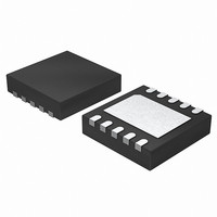
... NUMBER (°C) ISL9301IRZ 9301 - 3x3 DFN L10.3x3C ISL9301IRZ-T* 9301 - 3x3 DFN L10.3x3C *Please refer to TB347 for details on reel specifications. NOTE: These Intersil Pb-free plastic packaged products employ special Pb-free material sets, molding compounds/die attach materials, and 100% matte tin plate plus anneal (e3 termination finish, which is RoHS compliant and compatible with both SnPb and Pb-free soldering operations) ...

Page 2

... Thermal Information Thermal Resistance (Typical) DFN Package (Notes Maximum Junction Temperature (Plastic Package +150°C Maximum Storage Temperature Range . . . . . . . . . .-65°C to +150°C Pb-free Reflow Profile . . . . . . . . . . . . . . . . . . . . . . . . .see link below http://www.intersil.com/pbfree/Pb-FreeReflow.asp TEST CONDITIONS POR V = 3.0V, use PPR to indicate the comparator BAT output. ...

Page 3

Electrical Specifications Typical values are tested at VIN = 5V and the ambient temperature at +25°C. Range 100Ω; Parameters with MIN and/or MAX limits are 100% tested at +25°C, unless otherwise specified. L Temperature limits established by ...

Page 4

Block Diagram To USB or AC Adatper VIN ILIM REF VOUT VOUT_REF Die Temp 142 oC VCC TIME RTIME IMIN RIMIN Pin Descriptions VIN - Power input. The absolute maximum input voltage is 28V. A 10µF or larger value capacitor ...

Page 5

IREF - Charge-current program and monitoring pin. Connect a resistor between this pin and the GND pin to set the charge current limit determined by Equation 4: 3886 ( ) I ---------------- - mA = REF R IREF Where R ...

Page 6

Typical Application Circuit INPUT IREF R IMIN R TIME Theory of Operation When a valid input voltage is applied at VIN, the ISL9301 first regulates V at 4.5V for system power need. In the OUT ...

Page 7

The ISL9301 accepts an input voltage up to 28V but will be disabled when the input voltage exceeds the OVP threshold, minimum 10V, to protect against unqualified or faulty AC adapters. PPR Indication The PPR pin is an open-drain output ...

Page 8

I is set to 145mA is shown in Figure 2. Figure 3 REF shows a typical time domain charge current curve vs time and its accuracy limits for a complete cycle. The accuracy is compared against the voltage on ...

Page 9

X3 VIN TEMPERATURE MONITORING FIGURE 4. CHARGE CURRENT THERMAL FOLDBACK CIRCUIT +115°C FIGURE 5. CHARGE CURRENT FOLDBACK Applications Information Input Bypass Capacitor The input capacitor is required to suppress the power supply transient response during transitions. Typically, a 10µF or ...

Page 10

V is regulated at 4.5V, the charger is ON, delivering a OUT trickle charge current. The IC moves to a fast charge constant current mode when V reaches the V threshold. There are 3 possible BAT MIN states in this ...

Page 11

> < > ...

Page 12

... Accordingly, the reader is cautioned to verify that data sheets are current before placing orders. Information furnished by Intersil is believed to be accurate and reliable. However, no responsibility is assumed by Intersil or its subsidiaries for its use; nor for any infringements of patents or other rights of third parties which may result from its use ...

Related keywords