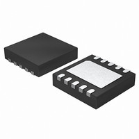
ISL9301IRZ-T Intersil, ISL9301IRZ-T Datasheet - Page 8

ISL9301IRZ-T
Manufacturer Part Number
ISL9301IRZ-T
Description
IC CHRGR LI-ION HV SGL 10-TDFN
Manufacturer
Intersil
Type
Battery Chargerr
Datasheet
1.ISL9301IRZ.pdf
(12 pages)
Specifications of ISL9301IRZ-T
Function
Charge Management
Battery Type
Lithium-Ion (Li-Ion), Lithium-Polymer (Li-Pol)
Voltage - Supply
4.3 V ~ 10 V
Operating Temperature
-40°C ~ 85°C
Mounting Type
Surface Mount
Package / Case
10-VFDFN Exposed Pad
Output Voltage
4.5V
Operating Supply Voltage (min)
4.3V
Operating Temp Range
-40C to 85C
Mounting
Surface Mount
Pin Count
10
Operating Temperature Classification
Industrial
Lead Free Status / RoHS Status
Lead free / RoHS Compliant
when I
shows a typical time domain charge current curve vs time
and its accuracy limits for a complete cycle. The accuracy is
compared against the voltage on the IREF pin. Thermal
foldback may affect the charge current curve as well as the
accuracy.
Dynamic Power Path Management
The power path management function of the ISL9301
controls the charge current and the system current when
charging with system load. This is based on the available
input current, which is either limited by the IC (800mA) or by
the input power source, whichever is smaller. When the
output voltage drops to the DPPM threshold (4.35V typical),
the dynamic power path management starts to function. The
DPPM control will first allocate the available current to the
system load, using the remaining current to charge the
battery. This is achieved by dynamically reducing the charge
current until V
needs more than the available current, V
I
CHG
FIGURE 3. CHARGE CURRENT ACCURACY WHEN
FIGURE 2. IREF PIN VOLTAGE vs CHARGE CURRENT (IREF
REF
1 5 0
TRICKLE
0
is set to 145mA is shown in Figure 2. Figure 3
I
REF
IS SET TO 150mA. THE DOTTED LINES SHOW
THE UPPER AND LOWER LIMITS OF THE
TOLERANCE)
OUT
= 145mA
is regulated. In the event that the system
CC
IR E F P IN V O L T A G E (V )
0.22I
0.12I
0.16I
REF
REF
REF
8
CV
0.9I
1.1I
REF
REF
I
REF
OUT
will continue to
TIME
1.3I
1 .2
1.0I
MIN
0.7I
MIN
MIN
ISL9301
drop. When V
DPPM control will turn on the charge control FET, allowing
the battery to supply current to the system load. Thus the
battery may be charged at a current smaller than the
programmed constant current.
Intelligent Timer
The internal timer in the ISL9301 provides a time reference
for the maximum charge time limit. The nominal clock cycle
for the reference time is set by the external resistor
connected between the TIME pin and GND and is given by
Equation 1.
The nominal maximum charge time interval is calculated
based on the assumption that the programmed charge
current is always available during the entire charging cycle.
However, due to the PPM control or due to the current limit
of the input source, or thermal foldback, the actual charge
current maybe reduced during the constant current charge
period. Under such conditions, the Intelligent Timer control
will increase the timeout interval accordingly to allow
approximately the same mAh product as the original timeout
interval at the programmed current.
Thermal Foldback
The thermal foldback function starts to reduce the charge
current when the internal temperature reaches a typical
value of +115°C. When thermal foldback is encountered, the
charge current will be reduced to a value where the die
temperature stops rising.
Figure 5 shows the thermal foldback operation whereas the
current signals at the summing node of the current error
amplifier CA are shown in Figure 4. I
the temperature tracking current generated from the
Temperature Monitoring block. The I
charge current until the internal temperature reaches
approximately +115°C; then I
meantime, as I
sum is a constant current IR). As a result, the charging
current, which is proportional to I
keeping the die temperature constant at +115°C.
The system output current, however, is not impacted by the
thermal foldback. Thus, when the charge current is reduced
to zero, if the die temperature still rises, the IC will shut down
to prevent damage to the IC.
OUT
T
rises, I
drops to below the battery voltage, the
SEN
will fall at the same rate (as the
T
starts to rise. In the
SEN
T
R
, also decreases,
has no impact on the
is the reference. I
July 2, 2008
FN6435.2
T
is


