X9530V14I Intersil, X9530V14I Datasheet - Page 4
X9530V14I
Manufacturer Part Number
X9530V14I
Description
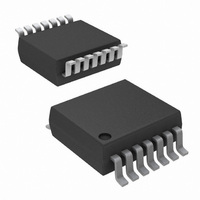
IC LASR CTRLR 1CHAN 5.5V 14TSSOP
Manufacturer
Intersil
Type
Laser Diode Controller (Fiber Optic)r
Datasheet
1.X9530V14IZT1.pdf
(28 pages)
Specifications of X9530V14I
Number Of Channels
1
Voltage - Supply
3 V ~ 5.5 V
Current - Supply
9mA
Operating Temperature
-40°C ~ 100°C
Package / Case
14-TSSOP
Mounting Type
Surface Mount
Lead Free Status / RoHS Status
Contains lead / RoHS non-compliant
Available stocks
Company
Part Number
Manufacturer
Quantity
Price
Company:

Part Number:
X9530V14I
Manufacturer:
Intersil
Quantity:
270


PRINCIPLES OF OPERATION
CONTROL AND STATUS REGISTERS
The Control and Status Registers provide the user
with a mechanism for changing and reading the value
of various parameters of the X9530. The X9530
contains seven Control, one Status, and several
Reserved registers, each being one Byte wide (See
Figure 1). The Control registers 0 through 6 are
located at memory addresses 80h through 86h
respectively. The Status register is at memory address
87h, and the Reserved registers at memory address
88h through 8Fh.
All bits in Control register 6 always power-up to the
logic state “0”. All bits in Control registers 0 through 5
power-up to the logic state value kept in their
corresponding
nonvolatile bits of a register retain their stored values
even when the X9530 is powered down, then powered
back up. The nonvolatile bits in Control 0 through
Control 5 registers are all preprogrammed to the logic
state “0” at the factory.
Bits indicated as “Reserved” are ignored when read,
and must be written as “0”, if any Write operation is
performed to their registers.
A detailed description of the function of each of the
Control and Status register bits follows:
Control Register 0
This register is accessed by performing a Read or
Write operation to address 80h of memory.
BL1, BL0: B
(N
These two bits are used to inhibit any write operation
to certain addresses within the memory array. The
protected region of memory is determined by the
values of the two bits as shown in the table below:
If the user attempts to perform a write operation to a
protected region of memory, the operation is aborted
without changing any data in the array.
0
0
1
1
ON
-
0
1
0
1
VOLATILE
Protected Addresses
00h to 7Fh (128 bytes)
00h to 7Fh and 90h to
00h to 7Fh and 90h to
LOCK
10Fh (256 bytes)
CFh (192 bytes)
None (Default)
)
nonvolatile
(Size)
L
OCK PROTECTION BITS
4
memory
Partition of array
GPM, LUT1, LUT2
None (Default)
GPM, LUT1
locked
cells.
GPM
The
X9530
Notice that if the Write Protect (WP) input pin of the
X9530 is active (LOW), then any write operation to
the memory is inhibited, irrespective of the Block
Lock bit settings.
VRM: V
(N
The VRM bit configures the Voltage Reference pin
(VRef) as either an input or an output. When the VRM
bit is set to “0” (default), the voltage at pin VRef is an
output from the X9530’s internal voltage reference.
When the VRM bit is set to “1”, the voltage reference
for the VRef pin is external. See Figure 2.
ADCIN: A/D C
(N
The ADCIN bit selects the input of the on-chip A/D
converter. When the ADCIN bit is set to “0” (default),
the output of the on-chip temperature sensor is the
input to the A/D converter. When the ADCIN bit is set
to “1”, the input to the A/D converter is the voltage at
the VSense pin. See Figure 4.
ADC
(N
When this bit is “1”, the status register at 87h is
updated after every conversion of the ADC. When this
bit is “0” (default), the status register is updated after
four consecutive conversions with the same result.
NV1234: C
TILITY MODE SELECTION BIT
When the NV1234 bit is set to “0” (default), bytes
written to Control registers 1, 2, 3, and 4 are stored in
volatile cells, and their content is lost when the X9530
is powered down. When the NV1234 bit is set to “1”,
bytes written to Control registers 1, 2, 3, and 4 are
stored in both volatile and nonvolatile cells, and their
value doesn’t change when the X9530 is powered
down and powered back up. See “Writing to Control
Registers” on page 17.
I1DS: C
(N
The I1DS bit sets the polarity of Current Generator 1,
DAC1. When this bit is set to “0” (default), the Current
Generator 1 of the X9530 is configured as a Current
Source. Current Generator 1 is configured as a
Current Sink when the I1DS bit is set to “1”. See
Figure 5.
ON
ON
ON
ON
FILT
-
-
-
-
VOLATILE
VOLATILE
VOLATILE
VOLATILE
URRENT
OLTAGE
O
ONTROL REGISTERS
FF
: ADC F
ONVERTER
)
)
)
G
R
)
ENERATOR
EFERENCE PIN
ILTERING
I
NPUT
1 D
(N
S
ON
IRECTION
1, 2, 3,
C
M
ELECT
ONTROL
ODE
-
VOLATILE
AND
November 11, 2005
S
ELECT
4
)
VOLA
FN8211.1
B
IT
-
Related parts for X9530V14I
Image
Part Number
Description
Manufacturer
Datasheet
Request
R

Part Number:
Description:
Temperature Compensated Laser Diode Controller
Manufacturer:
INTERSIL [Intersil Corporation]
Datasheet:

Part Number:
Description:
Temperature Compensated Laser Diode Controller
Manufacturer:
Intersil Corporation
Datasheet:
Part Number:
Description:
Intersil Corporation [CMOS Serial Controller Interface]
Manufacturer:
Intersil Corporation
Datasheet:
Part Number:
Description:
Manufacturer:
Intersil Corporation
Datasheet:
Part Number:
Description:
357-036-542-201 CARDEDGE 36POS DL .156 BLK LOPRO
Manufacturer:
Intersil Corporation
Datasheet:
Part Number:
Description:
1024-Word x 4-Bit LSI Static RAM
Manufacturer:
Intersil Corporation
Datasheet:
Part Number:
Description:
General Purpose NPN Transistor Arrays FN341.4
Manufacturer:
Intersil Corporation
Datasheet:
Part Number:
Description:
CMOS 16-Bit Microprocessor
Manufacturer:
Intersil Corporation
Datasheet:
Part Number:
Description:
Manufacturer:
Intersil Corporation
Datasheet:
Part Number:
Description:
Manufacturer:
Intersil Corporation
Datasheet:
Part Number:
Description:
Manufacturer:
Intersil Corporation
Datasheet:
Part Number:
Description:
Manufacturer:
Intersil Corporation
Datasheet:
Part Number:
Description:
CMOS 6-Bit Latch and Decoder Memory Interfaces
Manufacturer:
Intersil Corporation
Datasheet:
Part Number:
Description:
CA3046General Purpose NPN Transistor Arrays
Manufacturer:
Intersil Corporation
Datasheet:
Part Number:
Description:
Manufacturer:
Intersil Corporation
Datasheet: