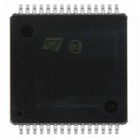
VNH3ASP30-E STMicroelectronics, VNH3ASP30-E Datasheet - Page 32

VNH3ASP30-E
Manufacturer Part Number
VNH3ASP30-E
Description
IC MOTOR DVR H BRDG 30-MPSO
Manufacturer
STMicroelectronics
Type
Half Bridge DC Motor Driverr
Datasheet
1.VNH3ASP30TR-E.pdf
(33 pages)
Specifications of VNH3ASP30-E
Applications
Automotive
Number Of Outputs
2
Current - Output
30A
Voltage - Supply
5.5 V ~ 16 V
Operating Temperature
-40°C ~ 150°C
Mounting Type
Surface Mount
Package / Case
30-MPSO, MultiPowerSO
Supply Current
10 mA
Mounting Style
SMD/SMT
Device Type
Motor
Module Configuration
Full Bridge
Peak Output Current
30A
Output Resistance
0.03ohm
Input Delay
250µs
Output Delay
250µs
Supply Voltage Range
5.5V To 36V
Rohs Compliant
Yes
Lead Free Status / RoHS Status
Lead free / RoHS Compliant
Voltage - Load
-
Lead Free Status / Rohs Status
Lead free / RoHS Compliant
Available stocks
Company
Part Number
Manufacturer
Quantity
Price
Part Number:
VNH3ASP30-E
Manufacturer:
ST
Quantity:
20 000
Revision history
6
32/33
Revision history
Table 18.
06-Feb-2008
01-Jun-2007
6-Feb-2007
Sep-2004
Dec-2005
Date
Document revision history
Revision
1
2
3
4
5
First issue
Resistance per leg modification
on page 21
Document converted into new ST template.
Changed
Removed Table 7. Thermal Data from page 4
Table 6: Power section on page
values for supply current in Off state and On state
Table 7: Logic inputs (INA, INB, ENA, ENB) on page
parameter descriptions for I
Table 8: PWM on page
and I
Table 10: Protection and diagnostic on page
except I
Table 11 on page
current drift
Section Table 13.: Truth table in fault conditions (detected on OUTA)
on page
Figure 6: Definition of the high-side switching times on page
Added vertical limitation line to left side of t
Figure 36: Waveforms in full-bridge operation (continued ) on
page
Added
Added
Added
Updated disclaimer on last page
Document reformatted.
Table 6: Power section on page
values for supply current in Off state
Corrected Heat Slug numbers in
functions.
PWH
24: Added dotted vertical limitation lines
Section 2.3: Electrical characteristics curves on page 16
Section 4: Package and PCB thermal data on page 25
Section 5: Package and packing information on page 29
LIM
14: Changed first of two fault conditions
Features on page 1
and V
CLP
11: Changed test conditions for K
Description of changes
10: Modified parameter descriptions for I
INL
to add ECOPACK
and I
9: Changed test conditions and max
9: changed test conditions and max
Figure 33: Half-bridge configuration
Table 3: Pin definitions and
INH
D(off)
10: Modified all symbols
®
arrow
package
2
9: Modified
VNH3ASP30-E
analog sense
13:
PWL


