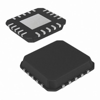
ISL6144IRZA-T Intersil, ISL6144IRZA-T Datasheet - Page 13

ISL6144IRZA-T
Manufacturer Part Number
ISL6144IRZA-T
Description
IC CTRLR MOSFET HV ORING 20-QFN
Manufacturer
Intersil
Datasheet
1.ISL6144IVZA.pdf
(29 pages)
Specifications of ISL6144IRZA-T
Applications
Telecom/Datacom Systems
Fet Type
N-Channel
Number Of Outputs
1
Internal Switch(s)
No
Delay Time - On
1ms
Delay Time - Off
250ns
Voltage - Supply
10 V ~ 75 V
Operating Temperature
-40°C ~ 105°C
Mounting Type
Surface Mount
Package / Case
20-VQFN Exposed Pad, 20-HVQFN, 20-SQFN, 20-DHVQFN
Lead Free Status / RoHS Status
Lead free / RoHS Compliant
Current - Supply
-
Available stocks
Company
Part Number
Manufacturer
Quantity
Price
Company:
Part Number:
ISL6144IRZA-T
Manufacturer:
Intersil
Quantity:
4 800
Using the ISL6144EVAL1Z High Voltage
ORing MOSFET Controller Evaluation
Board
In a multiple supply, fault tolerant, redundant power
distribution system, paralleled power supplies contribute
equally to the load current through various power sharing
schemes. Regardless of the scheme, a common design
practice is to include discrete ORing power diodes to protect
against reverse current flow should one of the power
supplies develop a catastrophic output short to ground. In
addition, reverse current can occur if the current sharing
scheme fails and an individual power supply voltage falls
significantly below the others.
Although the discrete ORing diode solution has been used
for some time and is inexpensive to implement, it has some
drawbacks. The primary downside is the increased power
dissipation loss in the ORing diodes as power requirements
for systems increase. In some systems this lack of efficiency
results in a cost that surpasses the cost of the ISL6144 and
power FET implementation. The power loss across a typical
ORing diode with 20A is about 10W. Many diodes will be
paralleled to help distribute the heat. In comparison, a FET
with 5mΩ on-resistance dissipates 2W, which constitutes an
80% reduction. When multiplied by the number of paralleled
supplies, the power savings are significant. Another
disadvantage when using an ORing diode would be failure to
detect a shorted or open ORing diode, jeopardizing power
system reliability. An open diode reduces the system to a
single point of failure while a diode short might pose a
hazard to technical personnel servicing the system while
unaware of this failure.
The ISL6144 ORing MOSFET Controller and a suitably
sized N-Channel power MOSFET(s) increase power
distribution efficiency and availability when replacing a
power ORing diode in high current applications. It can be
used in +9V to +75V systems and has an internal charge
pump to provide a floating gate drive for the N-Channel
ORing MOSFET.
The input/output differential trip point “V
programmed by two external resistors (R
This trip point can be adjusted to avoid false gate trip off due
to power supply noise.
The high speed comparator action protects the common bus
from being affected due to individual power supply shorts by
turning off the ORing MOSFET of the shorted feed in less
than 300ns (when using an ORing MOSFET with equivalent
gate to source capacitance equal to 39nF).
The Hysteretic Regulating (HR) Amplifier provides a slow
turn-off of the ORing MOSFET. This turn-off is achieved in
less than 100µs when one of the sourcing power supplies is
shutdown slowly for system diagnostics, ensuring zero
reverse current. This slow turn-off mechanism also reacts to
output voltage droop, degradation, or power-down.
13
OUT
1
, R
- V
2
or R
IN
” can be
6
, R
7
).
ISL6144
A circuit fault condition is indicated on an open drain FAULT
pin. The fault detection circuitry covers different types of
failures; including dead short in the sourcing supply, a
dead-short of any two ORing MOSFET terminals, or a blown
fuse in the power distribution path.
Typical Application
Related Literature
•
• Manufacturer’s MOSFET data sheets
PS_1
PS_2
- V
- LED1, LED2 are red LEDs to indicate a fault, different interfaces
used as the pull up source. In this case if it is higher than 16V,
use a zener diode from the FAULT pin to GND with a clamping
TB389
Guidelines for QFN (MLFP) Packages)
voltage less than the rating of the FAULT pin which is 16V.
are possible to the FAULT pin.
PU
R
R
R
C
C
C
CS
1
2
3
1
3
5
DC/DC
DC/DC
is an external pull up voltage source. Also, V
* TO C
= R
= R
= R
= C
= C
1
2
(PCB Land Pattern Design and Surface Mount
6
7
4
2
4
= 499Ω (5%)
= 47.5kΩ (5%)
= 1.21kΩ (5%)
= 150nF (10V)
= 10nF (10V)
RED
RED
8
R
R
C
* = 100nF *(100V) Optional Decoupling Caps
C
9V TO 75V
9V TO 75V
4
V
3
5
V
7
PU
*
*
PU
VIN2
VIN1
LED2
LED1
C
C1
3
VIN
HVREF
FAULT GND
VIN
HVREF
FAULT GND
ISL6144
ISL6144
GATE
GATE
U2
U1
COMP
Q
Q
COMP
VOUT
VOUT
VSET
VSET
1
1
R
R
6
1
OUT
C
R
R
C
C
January 6, 2011
8
7
2
2
6
*
can be
*
C
4
FN9131.6
VOUT


