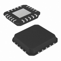
ISL6144IRZA-T Intersil, ISL6144IRZA-T Datasheet - Page 20

ISL6144IRZA-T
Manufacturer Part Number
ISL6144IRZA-T
Description
IC CTRLR MOSFET HV ORING 20-QFN
Manufacturer
Intersil
Datasheet
1.ISL6144IVZA.pdf
(29 pages)
Specifications of ISL6144IRZA-T
Applications
Telecom/Datacom Systems
Fet Type
N-Channel
Number Of Outputs
1
Internal Switch(s)
No
Delay Time - On
1ms
Delay Time - Off
250ns
Voltage - Supply
10 V ~ 75 V
Operating Temperature
-40°C ~ 105°C
Mounting Type
Surface Mount
Package / Case
20-VQFN Exposed Pad, 20-HVQFN, 20-SQFN, 20-DHVQFN
Lead Free Status / RoHS Status
Lead free / RoHS Compliant
Current - Supply
-
Available stocks
Company
Part Number
Manufacturer
Quantity
Price
Company:
Part Number:
ISL6144IRZA-T
Manufacturer:
Intersil
Quantity:
4 800
Detection of Power Feed Faults
The ISL6144 have two built-in mechanisms that monitor
voltages at VIN, VOUT and GATE pins. The first mechanism
monitors GATE with respect to VIN (with a 410mV threshold)
and the second mechanism monitors V
(with 370mV threshold). The open-drain FAULT pin will be
pulled low when any of the two above conditions is met.
Some of the typical system faults detected by the ISL6144 are:
Fault 1: Open Fuse at the Input Side
(Fuse has to be placed before the V
power supply and the source of the ORing MOSFET), note
that the EVAL board does not have footprint for installing this
fuse. This feature can be tested by adding a fuse externally.
The open fuse results in near zero current flow through the
ORing MOSFET, only a very low current drawn by the IC
bias will flow. The voltage at VIN pin is effectively
disconnected from the power source and will start dropping
slowly. The regulated source-drain voltage falls below its
20mV level and the gate of the MOSFET is pulled down and
turned off. GATE will become low and a fault is indicated with
internal built in delay (t
Fault 2: Drain to Source Short
In this case V
drop across the shorted MOSFET terminals will be close to
0V. The Gate will be pulled down and a fault will be
indicated. The resistance of the Drain to Source short
multiplied by the Drain short current must be low enough to
result in V
values), Otherwise this fault cannot be detected.
100µs/DIV
TIME SCALE
5V/DIV
FIGURE 26. MOSFET DRAIN TO SOURCE FAULT
V
G1
SD
< V
IN
is shorted to V
V
FWD_HR
IN
= 12V, FAULT PULLED TO +5V
FLT
(refer to data sheet for worst case
).
20
OUT
5V/DIV
V
OUT
, and in theory the voltage
IN
FAULT
5V/DIV
IN
tap, between the
with respect to VOUT
V
5V/DIV
IN1
ISL6144
Fault 3: MOSFET Gate to Source Dead Short
GATE voltage will be equal to V
fault is indicated.
Fault 4: ORing FET Off Condition
When V
flow. This means that if an ORing feed is not sharing current,
a fault will be indicated. Also if a feed (PS) is off while bias is
applied from V
Fault 5: MOSFET Gate to Drain Dead Short
In this case, the following condition will be violated GATE
<V
IN
+ 0.37V and a fault is issued.
5V/DIV
TIME SCALE
TIME SCALE
100µs/DIV
100µs/DIV
FIGURE 27. MOSFET GATE TO SOURCE FAULT
5V/DIV
V
IN
V
FIGURE 28. MOSFET GATE TO DRAIN FAULT
G1
G1
< V
OUT
OUT
V
V
IN
, the Gate is off to block reverse current
IN
to that feed, then a fault is also indicated.
= 12V, FAULT PULLED TO +5V
= 12V, FAULT PULLED TO +5V
IN
5V/DIV
, GATE <V
5V/DIV
V
V
OUT
OUT
FAULT
5V/DIV
FAULT
5V/DIV
IN
+ 0.37V and a
V
5V/DIV
V
5V/DIV
January 6, 2011
IN1
IN1
FN9131.6


