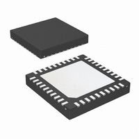
LP3971SQ-2G16/NOPB National Semiconductor, LP3971SQ-2G16/NOPB Datasheet - Page 17

LP3971SQ-2G16/NOPB
Manufacturer Part Number
LP3971SQ-2G16/NOPB
Description
IC PMU FOR APPL PROCESSORS 40LLP
Manufacturer
National Semiconductor
Series
PowerWise®r
Datasheet
1.LP3971SQ-B510NOPB.pdf
(50 pages)
Specifications of LP3971SQ-2G16/NOPB
Applications
Processor
Current - Supply
60µA
Voltage - Supply
2.7 V ~ 5.5 V
Operating Temperature
-40°C ~ 85°C
Mounting Type
Surface Mount
Package / Case
40-LLP
Lead Free Status / RoHS Status
Lead free / RoHS Compliant
Other names
LP3971SQ-2G16
LP3971SQ-2G16
LP3971SQ-2G16TR
LP3971SQ-2G16
LP3971SQ-2G16TR
V
I
V
PSRR
I
C
OUT
Q
Symbol
IN
OUT
OUT
Back-Up Charger Electrical Characteristics
Unless otherwise noted, V
in boldface type apply over the entire junction temperature range for operation, −40°C to +125°C. (Notes 2, 6) and (Note 8).
LP3971 Battery Switch Operation
The LP3971 has provisions for two battery connections, the
main battery Vbat and Backup Battery
The function of the battery switch is to connect power to the
RTC LDO from the appropriate battery, depending on condi-
tions described below:
•
matically connect the RTC LDO power to this battery.
•
matically connect the RTC LDO power to this battery
•
ficiently charged (Vbat > 3.1V), the switch will automatically
connect the RTC LDO power to the main battery.
•
nBATT_FLT will warn the system. Then if no action is taken
to restore the charge on the main battery, and discharging is
As the main battery is discharged a separate circuit called
If only the backup battery is applied, the switch will auto-
If both batteries are applied, and the main battery is suf-
If only the main battery is applied, the switch will auto-
Operational Voltage Range
Backup Battery Charging Current
Charger Termination Voltage
Backup Battery Charger Short Circuit
Current
Power Supply Ripple Rejection Ratio I
Quiescent Current
Output Capacitance
Output Capacitor ESR
Parameter
IN
= V
BATT
= 3.6V. Typical values and limits appearing in normal type apply for T
Voltage at V
V
Backup Battery Charger Enabled
(Note 8)
V
Enabled. Programmable
Backup_Bat = 0V, Backup Battery
Charger Enabled
V
f < 10 kHz
I
0 μA
OUT
OUT
IN
IN
OUT
= 3.6V, Backup_Bat = 2.5V,
= 5.0V Backup Battery Charger
≤
< 50 μA
≤
+ 0.4
50 μA, V
I
OUT
≤
≤
Conditions
IN
V
100 μA
BATT
OUT
17
= 3.15V
= V
continued the battery switch will disconnect the input of the
RTC_LDO from the main battery and connect to the backup
battery.
•
switched over from main to backup battery is 2.8V typically.
•
RTC LDO will not be reconnected to main battery until main
battery voltage is greater than 3.1V typically.
•
switch when only a main battery is used. This is accomplished
by setting the “no back up battery bit” in the control register
8h’0B bit 7 NBUB. With this bit set to “1”, the above described
switching will not occur, that is the RTC LDO will remain con-
nected to the main battery even as it is discharged below the
2.9V threshold. The Backup battery input should also be con-
nected to main battery.
IN
There is a hysteric voltage in this switch operation so; the
The system designer may wish to disable the battery
The main battery voltage at which the RTC LDO is
≤
5.0V
2.91
Min
3.3
5
Typ
190
3.1
0.1
15
25
9
J
= 25°C. Limits appearing
Max
500
5.5
www.national.com
Units
mΩ
mA
μA
dB
μA
μF
V
V


