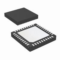
LP3971SQ-2G16/NOPB National Semiconductor, LP3971SQ-2G16/NOPB Datasheet - Page 41

LP3971SQ-2G16/NOPB
Manufacturer Part Number
LP3971SQ-2G16/NOPB
Description
IC PMU FOR APPL PROCESSORS 40LLP
Manufacturer
National Semiconductor
Series
PowerWise®r
Datasheet
1.LP3971SQ-B510NOPB.pdf
(50 pages)
Specifications of LP3971SQ-2G16/NOPB
Applications
Processor
Current - Supply
60µA
Voltage - Supply
2.7 V ~ 5.5 V
Operating Temperature
-40°C ~ 85°C
Mounting Type
Surface Mount
Package / Case
40-LLP
Lead Free Status / RoHS Status
Lead free / RoHS Compliant
Other names
LP3971SQ-2G16
LP3971SQ-2G16
LP3971SQ-2G16TR
LP3971SQ-2G16
LP3971SQ-2G16TR
INTERNAL THERMAL SHUTDOWN PROCEDURE
Thermal shutdown is build to generate early warning (typ.
125°C) which triggers the EXT_WAKEUP for the processor
acknowledge. When a thermal shutdown triggers (typ. 160°
C) the PMU will reset the system until the device cools down.
BATTERY SWITCH AND BACK UP BATTERY CHARGER
When Back-Up battery is connected but the main battery has
been removed or its supply voltage too low, LP3971 uses
Back-Up Battery for generating LDO_RTC voltage. When
Main Battery is available the battery fet switches over to the
main battery for LDO_RTC voltage. When Main battery volt-
age is too low or removed nBATT_FLT is asserted. If no back
The LP3971 has provision for two battery connections, the
main battery Vbat and Backup Battery (See Applications
Schematic Diagrams 1 & 2 of the LP3971 Data Sheet).
The function of the battery switch is to connect power to the
RTC LDO from the appropriate battery, depending on condi-
tions described below:
•
•
•
•
WAKEUP register bits
WUP0
WUP1
WUP2
WUP3
TSD_EW
If only the backup battery is applied, the switch will
automatically connect the RTC LDO power to this battery.
If only the main battery is applied, the switch will
automatically connect the RTC LDO power to this battery.
If both batteries are applied, and the main battery is
sufficiently charged (V
automatically connect the RTC LDO power to the main
battery.
As the main battery is discharged by use, the user will be
warned by a separate circuit called nBATT_FLT. Then if
no action is taken to restore the charge on the main
battery, and discharging is continued the battery switch will
protect the RTC LDO by disconnecting from the main
battery and connecting to the backup battery.
GPIO<1>
GPIO<1>
X
X
X
1
0
1
0
1
0
1
0
1
GPIO<1>
GPIO<1>
X
X
X
0
0
0
1
1
0
0
1
1
BAT
> 3.1V), the switch will
Controls
Reason for WAKEUP
SPARE
TEST_JIG
PWR_ON short pulse
PWR_ON long pulse
TSD Early Warning
Nextchgen_sel
Factory fm disabled
1
1
1
X
0
0
0
0
bucen
41
0
0
X
1
X
X
X
X
up battery exists, the battery switch to back up can be
switched off by nBU_BAT_EN bit. User can set the battery
fault determination voltage and battery charger current via
I
can be done via serial interface (nBAT_CHG_EN) or external
charger enable pin (nCHG_EN). Pin 29 is set as external
charger enable input by default. A SHUTBKUPBAT register
bit can be used to avoid discharging back up battery during
storage etc. By setting this bit before removing main battery
the back up battery connection will not draw any current and
stays like this until the bit is set to default or the system is
reset.
GENERAL PURPOSE I/O FUNCTIONALITY (GPIO1 AND
GPIO2)
LP3971 has 2 general purpose I/Os for system control. I
compatible interface will be used for setting any of the pins to
input, output or hi-Z mode. Inputs value can be read via serial
interface (GPI1,2 bits). The pin 29 functionality needs to be
set to GPIO by serial interface register bit nEXTCHGEN.
(GPIO/CHG)
•
REGULATED VOLTAGES OK
All the power domains have own register bit (X_OK) that pro-
cessor can read via serial interface to be sure that enabled
powers are OK (regulating). Note that these read only bits are
only valid when regulators are settled (avoid reading these
bits during voltage change or power up).
2
C compatible interface. Enabling of back up battery charger
— The main battery voltage at which the RTC LDO is
— There is a hysterisis voltage in this switch operation so,
Additionally, the user may wish to disable the battery
switch, such as, in the case when only a main battery is
used. This is accomplished by setting the “no back up
battery bit” in the control register 8h’89 bit 7 NBUB. With
this bit set to “1”, the above described switching will not
occur, that is the RTC LDO will remain connected to the
main battery even as it is discharged below the 2.9 Volt
threshold.
switched from main to backup battery is 2.9V typically.
the RTC LDO will not be reconnected to main battery
until main battery voltage is greater than 3.1V typically.
Port Function
Input (dig)->
GPIO_tstiob
Output = 0
Output = 1
Input = 0
Input = 1
GPIO1
HiZ
X
X
1
1
1
1
Gpin 1
Input
Reg
Input (dig)->
Output = 0
Output = 1
0
0
0
0
0
GPIO2
HiZ
Not Enabled
batmonchg
Function
Enabled
Enabled
www.national.com
gpin2
input
0
0
0
2
C


