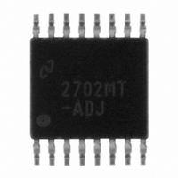
LM2702MT-ADJ/NOPB National Semiconductor, LM2702MT-ADJ/NOPB Datasheet - Page 15

LM2702MT-ADJ/NOPB
Manufacturer Part Number
LM2702MT-ADJ/NOPB
Description
IC MODULE PANEL TFT DISP 16TSSOP
Manufacturer
National Semiconductor
Datasheet
1.LM2702MT-ADJNOPB.pdf
(21 pages)
Specifications of LM2702MT-ADJ/NOPB
Applications
LCD Display
Current - Supply
2.6mA
Voltage - Supply
2.2 V ~ 12 V
Operating Temperature
-40°C ~ 125°C
Mounting Type
Surface Mount
Package / Case
16-TSSOP
Lead Free Status / RoHS Status
Lead free / RoHS Compliant
Other names
*LM2702MT-ADJ
*LM2702MT-ADJ/NOPB
LM2702MT-ADJ
*LM2702MT-ADJ/NOPB
LM2702MT-ADJ
Operation
CONTINUOUS CONDUCTION MODE
The LM2702 is a TFT Panel Module containing a current-
mode, PWM boost regulator. A boost regulator steps the
input voltage up to a higher output voltage. In continuous
conduction mode (when the inductor current never reaches
zero at steady state), the boost regulator operates in two
cycles.
In the first cycle of operation, shown in Figure 1 (a), the
transistor is closed and the diode is reverse biased. Energy
is collected in the inductor and the load current is supplied by
C
The second cycle is shown in Figure 1 (b). During this cycle,
the transistor is open and the diode is forward biased. The
energy stored in the inductor is transferred to the load and
output capacitor.
The ratio of these two cycles determines the output voltage.
The output voltage is defined approximately as:
where D is the duty cycle of the switch, D and D' will be
required for design calculations
OUT
.
(a) First Cycle of Operation (b) Second Cycle Of Operation
FIGURE 1. Simplified Boost Converter Diagram
15
SETTING THE OUTPUT VOLTAGE
The output voltage is set using the feedback pin and a
resistor divider connected to the output as shown in the
typical operating circuit. The feedback pin voltage is 1.265V,
so the ratio of the feedback resistors sets the output voltage
according to the following equation:
SOFT-START CAPACITOR
The LM2702 has patented internal circuitry that is used to
limit the inductor inrush current on start-up of the boost
DC/DC switching regulator. This inrush current limiting cir-
cuitry serves as a soft-start. However, many applications
may require much more soft-start than what is available with
the internal circuitry. The external SS pin is used to tailor the
soft-start for a specific application. A 12µA current charges
the external soft-start capacitor, C
be estimated as:
The minimum soft-start time is set by the internal soft-start
circuitry, typically 7ms. Only longer soft-start times may be
implemented using the SS pin and a capacitor C
shorter time is designed for using the above equation, the
internal soft-start circuitry will override it.
Due to the unique nature of the dual internal/external soft-
start, care was taken in the design to ensure temperature
stable operation. As you can see with the Iss data in the
Electrical Characterisitcs table and the graph "Soft-Start
Current vs. V
IN
" in the Typical Performance Characterisitcs
T
SS
= C
SS
*0.6V/12µA
SS
. The soft-start time can
20051102
www.national.com
SS
. If a


