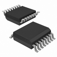
NE1617ADS,112 NXP Semiconductors, NE1617ADS,112 Datasheet - Page 23

NE1617ADS,112
Manufacturer Part Number
NE1617ADS,112
Description
IC TEMP MONITOR 16SSOP
Manufacturer
NXP Semiconductors
Datasheet
1.NE1617ADS118.pdf
(27 pages)
Specifications of NE1617ADS,112
Function
Temp Monitoring System (Sensor)
Topology
ADC, Multiplexer, Register Bank
Sensor Type
External & Internal
Sensing Temperature
-55°C ~ 125°C, External Sensor
Output Type
SMBus™
Output Alarm
Yes
Output Fan
No
Voltage - Supply
3 V ~ 5.5 V
Operating Temperature
-55°C ~ 125°C
Mounting Type
Surface Mount
Package / Case
16-QSOP
Temperature Sensor Function
Temp Sensor
Interface Type
Serial (2-Wire)
Operating Temperature (min)
0C
Operating Temperature (max)
125C
Operating Temperature Classification
Military
Operating Supply Voltage (min)
3V
Operating Supply Voltage (typ)
3.3/5V
Operating Supply Voltage (max)
5.5V
Lead Free Status / RoHS Status
Lead free / RoHS Compliant
Other names
935268119112
NE1617ADS
NE1617ADS
NE1617ADS
NE1617ADS
NXP Semiconductors
14. Mounting
NE1617A_4
Product data sheet
14.1 Printed-circuit board layout consideration
For further information on temperature profiles, refer to Application Note AN10365
“Surface mount reflow soldering description” .
Because the NE1617A is used to measure a very small voltage in the range of microvolts
from the remote sensor, care must be taken to minimize noise induced at the sensor
inputs, especially in the computer motherboard noisy environment. The following
precautions should be considered:
Fig 14. Temperature profiles for large and small components
•
•
•
•
•
•
Place the NE1617A as close as possible to the remote sensor. It can be from 4 inches
to 8 inches, as long as the worst noise sources such as clock generator, data and
address buses, CRTs are avoided.
Route the D+ and D lines in parallel and close together with ground guards enclosed
(refer to
Leakage currents due to printed-circuit board contamination could affect the
temperature accuracy and must be considered. Error can be introduced by the
leakage current as shown on the characteristics curve
versus printed-circuit board leakage
Use wide tracks to reduce inductance and noise pickup that may be introduced by
narrow ones. The width of 10 mil and space of 10 mil are recommended.
Place a bypass capacitor of 0.1 F close to the V
2200 pF close to the D+ and D pins.
If the remote sensor is operating in a noisy environment and located several feet away
from the NE1617A, a shielded twisted pair cable is recommended. Make sure the
shield of the cable is connected to the NE1617A ground pin (GND), and leave the
shield at the remote end unconnected. Shield connecting to ground of both ends
temperature
MSL: Moisture Sensitivity Level
Figure
15).
Rev. 04 — 30 July 2009
= minimum soldering temperature
maximum peak temperature
minimum peak temperature
= MSL limit, damage level
Temperature monitor for microprocessor systems
resistance”.
DD
pin and an input filter capacitor of
Figure 6 “Temperature error
temperature
peak
NE1617A
© NXP B.V. 2009. All rights reserved.
001aac844
time
23 of 27


