ISL6401CB Intersil, ISL6401CB Datasheet
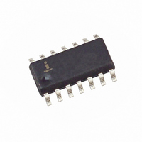
IC CONTROLLER PWM SYNC 14-SOIC

ISL6401CB

Manufacturer Part Number
ISL6401CB
Description
IC CONTROLLER PWM SYNC 14-SOIC
Manufacturer
Intersil
Datasheet

Specifications of ISL6401CB

Pwm Type
Current Mode
Number Of Outputs
1
Frequency - Max
600kHz
Duty Cycle
50%
Voltage - Supply
4.5 V ~ 5.5 V
Buck
No
Boost
Yes
Flyback
Yes
Inverting
No
Doubler
No
Divider
No
Cuk
No
Isolated
Yes
Operating Temperature
-40°C ~ 85°C
Package / Case
14-SOIC (3.9mm Width), 14-SOL
Frequency-max
600kHz
Rohs Compliant
YES
Lead Free Status / RoHS Status
Contains lead / RoHS non-compliant

Available stocks

Company
Part Number
Manufacturer
Quantity
Price
Part Number:
ISL6401CB
Manufacturer:
SILICONIX
Quantity:
82
Part Number:
ISL6401CB
Manufacturer:
INTERSIL
Quantity:
20 000
Company:
Part Number:
ISL6401CB-T
Quantity:
378
Part Number:
ISL6401CBZ
Manufacturer:
Intersil
Quantity:
100
Company:
Part Number:
ISL6401CBZ
Quantity:
20
Synchronizing Current Mode PWM for
Subscriber Line Interface Circuits (SLICs)
The ISL6401 adjustable frequency, low power, pulse width
modulating (PWM) current mode controller is designed for a
wide range of DC/DC conversion applications including
boost, flyback, and isolated output configurations. The
device is optimized to provide a high performance, low-cost
solution for Ringing SLIC (RSLIC) ring and talk power
supplies. An integrated inverter allows for easy design of
negative voltage regulation circuits with a minimal amount of
external components. Internal soft-start minimizes start-up
stress without any external components. Peak current mode
control effectively handles Ring trip transients and provides
inherent overcurrent protection.
This advanced BiCMOS design features low operating
current, adjustable operating output frequency (50kHz to
600kHz), internal soft-start and a SYNC input that allows the
oscillator to be locked to an external clock for noise sensitive
applications. DC/DC conversion efficiency is optimized by
use of a low current sense voltage. A logic level shutdown
input is included, which reduces supply current to 55µA in
the shutdown mode.
Pinouts
COMP
SYNC
NFB OUT
CT
FB
NFB IN
COMP
SYNC
SD
1
2
3
4
CT
FB
16
ISL6401 (SOIC)
1
2
3
4
5
6
7
5
ISL6401 (QFN)
TOP VIEW
TOP VIEW
®
15
6
1
14
7
Data Sheet
13
8
14
13
12
10
11
9
8
12
10
11
9
V
PV
GATE
PGND
GND
CS
NC
CC
PGND
PGND
GND
CS
CC
1-888-INTERSIL or 1-888-352-6832
CAUTION: These devices are sensitive to electrostatic discharge; follow proper IC Handling Procedures.
Features
• Positive and Negative Output Regulation
• Starting Supply Current . . . . . . . . . . . . . . . . . 100µA (typ.)
• Quiescent Current . . . . . . . . . . . . . . . . . . . . . . 55µA (typ.)
• Output Frequency Range. . . . . . . . . . . . 50kHz to 600kHz
• External Clock Synchronization
• Fast Transient Response with Peak Current Mode Control
• Internal Soft-Start
• Drives N-Channel MOSFET
• Logic Level Shutdown
• Leading Edge Blanking
• 1% Tolerance Voltage Reference Over Line and
• Pb-Free Available (RoHS Compliant)
Applications
• VoIP/VoDSL Ringer and Off-Hook Voltage Generators
• Multi-Output Flyback Supplies
• Cable and DSL Modems
• Set-Top Boxes
• Wireless Local Loops
• LMDH and FTTH Supplies
• Boost Regulators
• Routers
Ordering Information
Add -T suffix for tape and reel packaging.
NOTES:
ISL6401CB
ISL6401CBZ (Note)
ISL6401CR
ISL6401CRZ (Note)
1. The parts with suffix ‘C’ are being tested to the industrial temperature
2. Intersil Pb-free products employ special Pb-free material sets; molding
PART NUMBER
Temperature
grade. This has been updated in the table above. The IB and IR parts are
being discontinued. The affected parts are: ISL6401IB, ISL6401IBZ,
ISL6401IB-T, ISL6401IBZ-T, ISL6401IR, ISL6401IRZ, ISL6401IR-T,
ISL6401IRZ-T.
compounds/die attach materials and 100% matte tin plate termination
finish, which are RoHS compliant and compatible with both SnPb and Pb-
free soldering operations. Intersil Pb-free products are MSL classified at
Pb-free peak reflow temperatures that meet or exceed the Pb-free
requirements of IPC/JEDEC J STD-020.
All other trademarks mentioned are the property of their respective owners.
April 13, 2005
|
Intersil (and design) is a registered trademark of Intersil Americas Inc.
Copyright © Intersil Americas Inc. 2001-2005. All Rights Reserved
RANGE (°C)
-40 to 85
-40 to 85
-40 to 85
-40 to 85
TEMP.
14 Ld SOIC
14 Ld SOIC (Pb-free)
16 Ld 4x4 QFN
16 Ld 4x4 QFN (Pb-free) L16.4x4
PACKAGE
ISL6401
FN9007.7
M14.15
M14.15
L16.4x4
DWG. #
PKG.

Related parts for ISL6401CB

ISL6401CB Summary of contents

Page 1

... Boost Regulators PGND • Routers GND Ordering Information CS NC PART NUMBER ISL6401CB ISL6401CBZ (Note) ISL6401CR ISL6401CRZ (Note) Add -T suffix for tape and reel packaging. PGND 12 NOTES: PGND 11 1. The parts with suffix ‘C’ are being tested to the industrial temperature grade ...

Page 2

... GND 6 NFB NFB_IN NC 10K R3 ISL6401 1.24K NOTES fit as close as possible to transformer IFLY0012 contacts: Coilcraft: (847) 516-7377 GCI Technology: (972) 423-8411 ext. 245 5. For custom specific designs or questions please contact Intersil at 1-888-INTERSIL or 321-724-7143. 2 ISL6401 GND VCC 200K VOLTAGE REFERENCE IBIAS ICSCOMP ILIM ...

Page 3

Absolute Maximum Ratings Supply Voltage GND -0.3V to +7.0V CC, CC PGND to GND . . . . . . . . ...

Page 4

Electrical Specifications Recommended operating conditions unless otherwise noted. Refer to Block Diagram and Typical Application schematic. V PARAMETER Start to Stop Hysteresis SOFT-START - DIGITAL COMP Rise Time OSCILLATOR Gate Output Frequency Gate Output Frequency Range Temperature Stability Sync. Frequency ...

Page 5

Typical Performance Curves 5.0 4.5 4.0 3.5 3.0 2.5 2.0 1.5 1.0 0.5 0 -40 -20 25 TEMPERATURE (°C) FIGURE 3. SUPPLY CURRENT vs TEMPERATURE Pin Descriptions SD - This pin is logic level compatible and can be pulled high, ...

Page 6

Total V the sum of the quiescent V current and the average CC output current. Knowing the operating frequency and the MOSFET gate charge (Qg), average output current can be calculated from: × I ...

Page 7

... ISL6401 Flyback Reference Design The Typical Application Schematic shows a current mode power supply using the Intersil ISL6401 in a standard flyback topology. The IC requires +5V Bias. The application circuit is intended for wall adapters that power home gateway/router boxes ...

Page 8

Switching losses are the result of overlapping drain current and source voltage at turn-off. The drain voltage begins to rise only after the miller capacitance of the device begins to discharge. This discharging time is a function of the external ...

Page 9

Primary Inductance The flyback transformer is actually a coupled inductor, acting as an energy storage unit, as well as performing the usual transformer functions. Crucial considerations include primary inductance, working flux density swing, gap length, the winding scheme and wire ...

Page 10

Small Outline Plastic Packages (SOIC) N INDEX 0.25(0.010) H AREA E - SEATING PLANE - -C- α µ 0.10(0.004) 0.25(0.010 NOTES: 1. Symbols are defined in ...

Page 11

... Accordingly, the reader is cautioned to verify that data sheets are current before placing orders. Information furnished by Intersil is believed to be accurate and reliable. However, no responsibility is assumed by Intersil or its subsidiaries for its use; nor for any infringements of patents or other rights of third parties which may result from its use ...

Related keywords