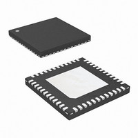
ISL9502CRZ Intersil, ISL9502CRZ Datasheet

ISL9502CRZ
Specifications of ISL9502CRZ
Related parts for ISL9502CRZ
ISL9502CRZ Summary of contents
Page 1
... ISL9502CRZ ISL9502CRZ -10 to 100 48 Ld 7x7 QFN (Note) ISL9502CRZ-T ISL9502CRZ -10 to 100 48 Ld 7x7 QFN (Note) NOTE: Intersil Pb-free plus anneal products employ special Pb-free material sets; molding compounds/die attach materials and 100% matte tin plate termination finish, which are RoHS compliant and compatible with both SnPb and Pb-free soldering operations ...
Page 2
Pinout VDIFF VSEN RTN DROOP DFB VO VSUM VIN GND VDD ISEN2 ISEN1 2 ISL9502 ISL9502 (7x7 QFN) TOP VIEW GND PAD (BOTTOM) GND NC SET2 SET1 VR_ON VSEL5 VSEL4 VSEL3 VSEL2 VSEL1 VSEL0 GND FN9275.1 July 17, 2006 ...
Page 3
Absolute Maximum Ratings Supply Voltage, VDD . . . . . . . . . . . . . . . . . . . . . . . . . . . . . -0.3 -+7V Input Voltage, VIN ...
Page 4
Electrical Specifications PARAMETER ISEN Imbalance Voltage Input Bias Current SOFT-START CURRENT Soft-Start Current GATE DRIVER DRIVING CAPABILITY UGATE Source Resistance R UGATE Source Current I SRC(UGATE) UGATE Sink Resistance R UGATE Sink Current I SNK(UGATE) ...
Page 5
Electrical Specifications PARAMETER Leakage Current of SET1 DAC(VSEL0-VSEL5), SET3 and SET2 Inputs Low DAC(VSEL0-VSEL5), SET3 and SET2 Inputs High Leakage Current of DAC(VSEL0- VSEL5), SET3 and SET2 THERMAL MONITOR NTC Source Current Over-temperature Threshold VRHOT# ...
Page 6
DROOP - Output of the droop amplifier. The voltage level on this pin is the sum of Vo and the programmed droop voltage by the external resistors. DFB - Inverting input to droop amplifier input to the ...
Page 7
Functional Block Diagram 60µA PVCC PVCC VDD VIN VIN ISEN2 CURRENT BALANCE ISEN1 VDD PGOOD PGOOD MONITOR AND LOGIC P FLT GOOD FAULT AND PGOOD LOGIC RBIAS DAC FIGURE 1. SIMPLIFIED FUNCTIONAL BLOCK DIAGRAM OF ISL9502 7 ISL9502 PVCC PVCC ...
Page 8
Typical Performance Curves 100 12. 19. (A) OUT FIGURE 2. 2-PHASE CCM EFFICIENCY, ...
Page 9
Typical Performance Curves OUT FIGURE 8. 8V-20V INPUT LINE TRANSIENT RESPONSE 240µ OUT FIGURE 10. LOAD STEP-UP RESPONSE, 35A LOAD STEP @ 200A/µs, 2 PHASE CCM V OUT FIGURE 12. LOAD ...
Page 10
Typical Performance Curves DROP PHASE IN SET3 CCM MODE V CORE PHASE1 PHASE2 FIGURE 14. 2-PHASE CCM TO 1-PHASE CCM, AT SET1 = 0, SET2 = 10A LOAD V OUT PGOOD IL1, IL2 FIGURE 16. OVERCURRENT PROTECTION ...
Page 11
Simplified Application Circuit for DCR Current Sensing VSEL<0:5> VR_ON GPUGOOD REMOTE SENSE FSET C 9 FIGURE 19. ISL9502 BASED TWO-PHASE BUCK ...
Page 12
Simplified Application Circuit for Resistive Current Sensing VSEL<0:5> SET2 SET1 SET3 VR_ON GPUGOOD REMOTE SENSE FSET C 9 FIGURE 20. ISL9502 ...
Page 13
Theory of Operation The ISL9502 is a two-phase regulator including embedded gate drivers for reduced system cost and board area. The regulator provides optimum steady-state and transient performance for GPU applications up to 60A. System efficiency is enhanced by idling ...
Page 14
As the load current increases from zero, the output voltage will droop from the VSEL table value by an amount proportional to current to achieve active voltage positioning. The ISL9502 provides for current to be measured using either resistors in ...
Page 15
While transitioning to single-phase operation, the controller smoothly transitions current from the idling-phase to the active-phase, and detects the idling-phase zero-current condition. During transitions into DCM or CCM mode, the timing is carefully adjusted to eliminate output voltage excursions. When ...
Page 16
Refer to Figure 17, the second level of overvoltage protection behaves differently. If the output exceeds 1.7V fault is immediately declared, PGOOD is latched low and the low-side FETs are turned on. The low-side FETs will remain on ...
Page 17
Static Mode of Operation - Remote Differential Sensing Remote differential sensing is the ability of the controller to regulate the core output voltage at a remotely sensed point. This allows the voltage regulator to compensate for various resistive drops in ...
Page 18
In general, the lighter the load, the slower the switching frequency. Therefore, the switching loss is much reduced for the light load operation, which is important for conserving the battery power in the portable application. Voltage Regulator Thermal Throttling The ...
Page 19
Once the NTC thermistor resistor is determined, the series resistor can be derived by: 1.18V ( ) R = --------------- - R – 19.67kΩ R – S NTC 60µA Once R and R is designed, the actual NTC ...
Page 20
... Rseries = 2610kΩ, and Rpar = 11kΩ, RS generates a desired G1, close to the feature specified in Equation 20. The actual G1 at 25°C is 0.763. For different G1 and NTC thermistor preference, the design file to generate the proper value of Rntc, Rseries, Rpar, and RS is provided by Intersil. EQV 20 ISL9502 OCSET VSUM ...
Page 21
A good compensation can limit the drift to 2mV. If the output voltage is decreasing with temperature increase, that ratio between the NTC thermistor value and the rest of the resistor ...
Page 22
The ISL9502 uses RC filter to sense the average voltage on phase node and forces the average voltage on the phase node to be equal for current balance. Even though the ISL9502 forces the ISEN voltages to be almost equal, ...
Page 23
Note, if the droop load line slope is not 0.0018 (V/A) in the application, the overcurrent setpoint will differ from predicted. 10µ DROOP INTERNAL TO ISL9502 + VDIFF RTN VSEN ...
Page 24
... Accordingly, the reader is cautioned to verify that data sheets are current before placing orders. Information furnished by Intersil is believed to be accurate and reliable. However, no responsibility is assumed by Intersil or its subsidiaries for its use; nor for any infringements of patents or other rights of third parties which may result from its use ...


